Differential Speed Reciprocating Piston Internal Combustion Engine

Inactive Publication Date: 2009-06-25
CHU ZHAODING
View PDF5 Cites 74 Cited by
  • Summary
  • Abstract
  • Description
  • Claims
  • Application Information

AI Technical Summary

Problems solved by technology

Thus, the exergy of the working medium fails to be converted into mechanic power quickly and efficiently, but degenerating into anergy and losing its working capacity permanently, leading to poor energy efficiency.
However, various prob

Method used


Image

  • Differential Speed Reciprocating Piston Internal Combustion Engine
  • Differential Speed Reciprocating Piston Internal Combustion Engine
  • Differential Speed Reciprocating Piston Internal Combustion Engine

Examples


implementation example i

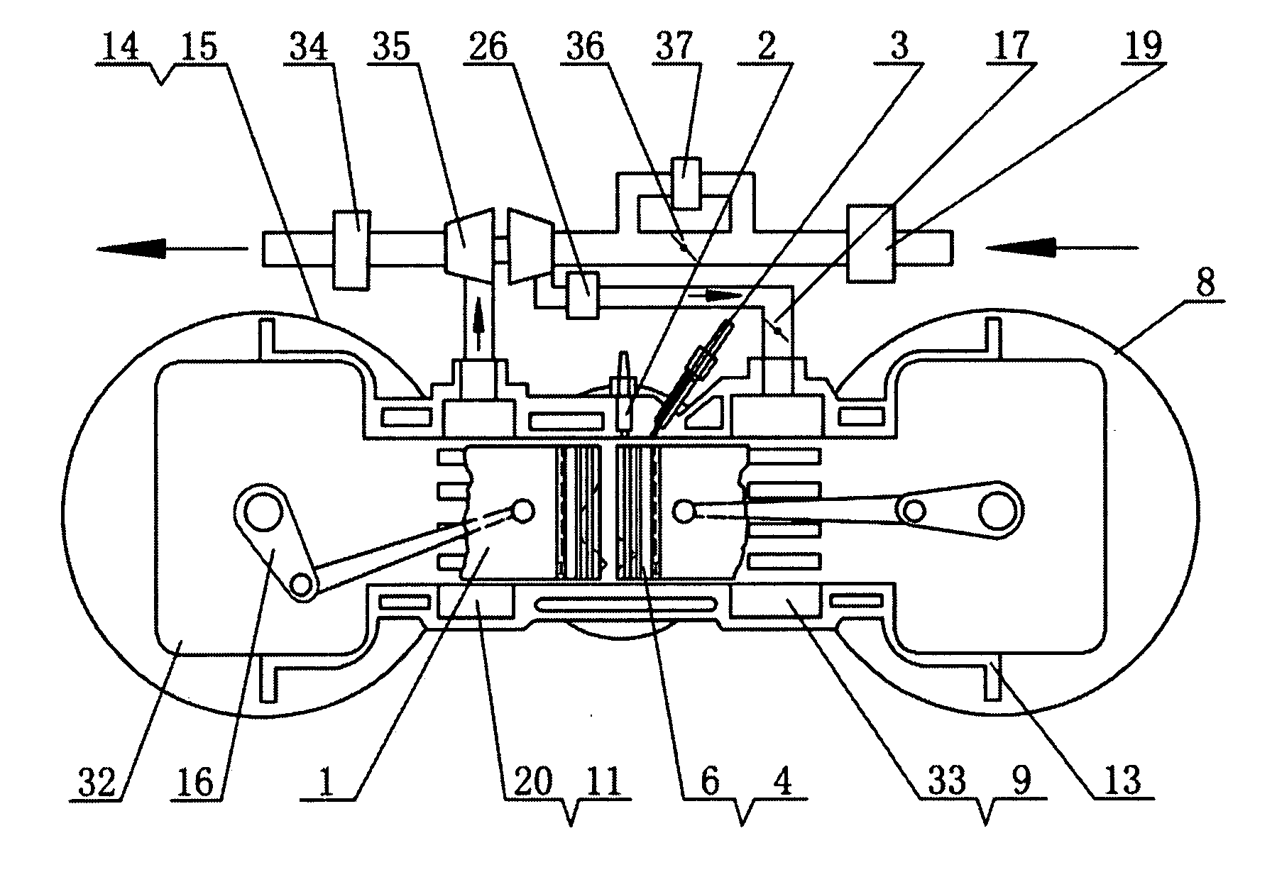
[0059]FIG. 9 shows an example of implementation. It is a small gasoline engine, and includes power piston 1, spark plug 2, fuel injector 3, auxiliary piston 4, auxiliary crankcase scavenging pipe 5, auxiliary crank connecting rod mechanism 6, auxiliary crankcase intake pipe 7, auxiliary crankshaft flywheel 8, scavenging port 9, power crankcase scavenging pipe 10, exhaust port 11, cylinder water jacket 12, cylinder body 13, power crankshaft flywheel 14, coordination mechanism 15, power crank connecting rod mechanism 16, throttle 17, intake pipe 18, air filter 19, exhaust manifold 20, and crankcase 32.

[0060]Two crankcases 32 are located at the two ends of cylinder body 13 respectively, auxiliary crank connecting rod mechanism 6 and power crank connecting rod mechanism 16 are placed in two crankcases 32, power piston 1 and auxiliary piston 4 are placed inside cylinder body 13 in opposite directions, auxiliary crank connecting rod mechanism 6 is connected to auxiliary piston 4, power cr...

implementation example ii

[0061]FIG. 10 shows a second implementation example. It is a gasoline direct injection (GDI) compound charging engine, and includes power piston 1, park plug 2, fuel injector 3, auxiliary piston 4, auxiliary crank connecting rod mechanism 6, auxiliary crankshaft flywheel 8, scavenging port 9, exhaust port 11, cylinder body 13, power crankshaft flywheel 14, coordination mechanism 15, power crank connecting rod mechanism 16, throttle 17, air filter 19, exhaust manifold 20, crankcase 32, intake passage 33, exhaust gas treatment unit 34, exhaust gas turbo charger 35, adjusting valve 36, and Roots blower 37.

[0062]Two crankcases 32 are located on the two ends of cylinder body 13 respectively, auxiliary crank connecting rod mechanism 6 and power crank connecting rod mechanism 16 are inside crankcases 32, power piston 1 and auxiliary piston 4 are placed in opposite directions inside cylinder body 13, auxiliary crank connecting rod mechanism 6 is connected to auxiliary piston 4, power crank ...

implementation example iii

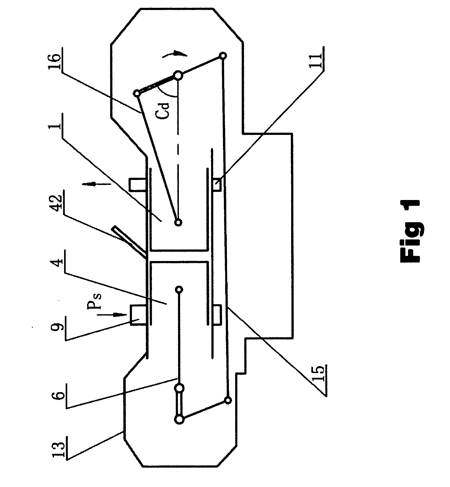
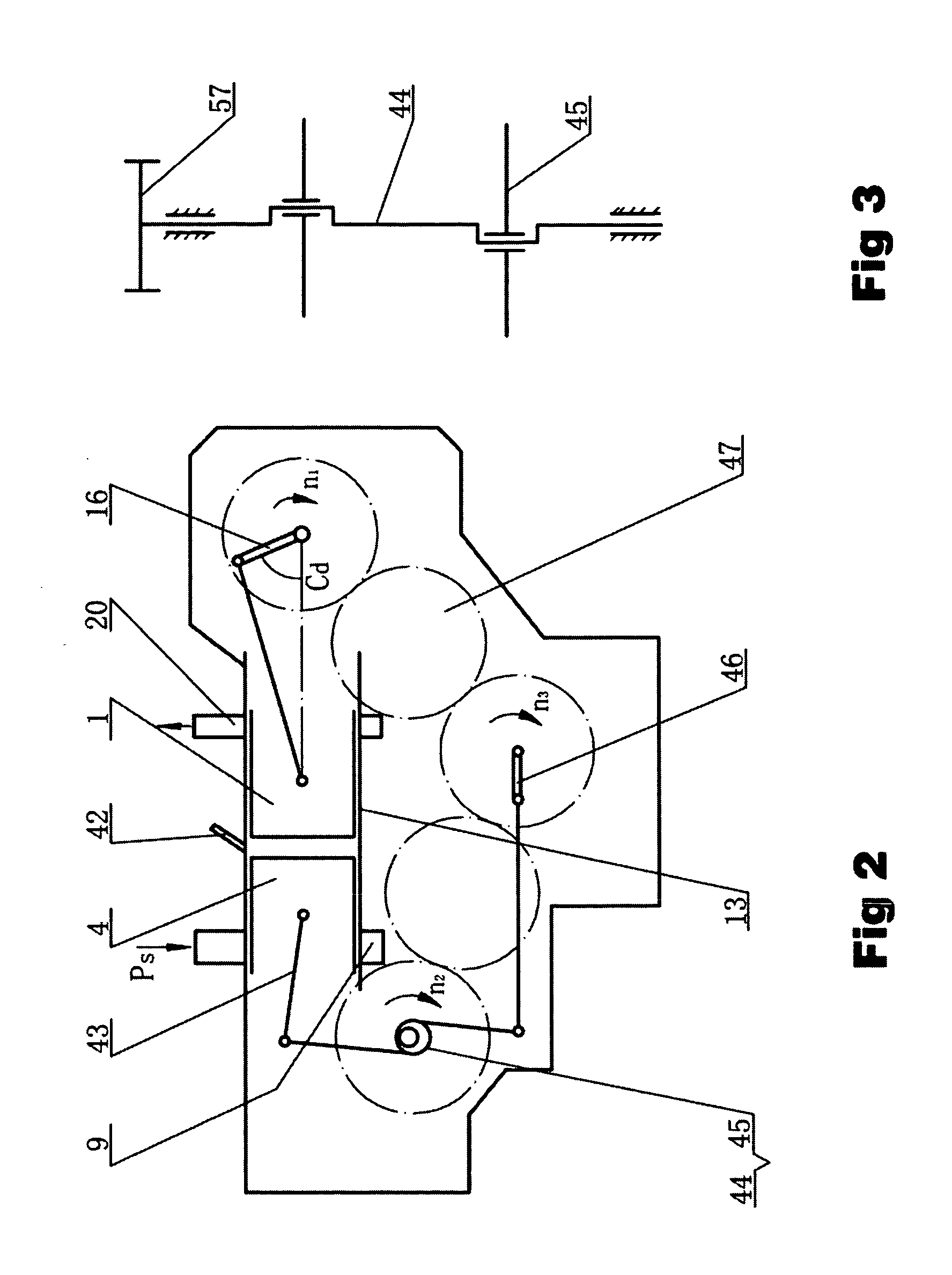
[0064]FIG. 11 shows a third implementation example. It is a variable compression ratio horizontal differential speed reciprocating internal combustion engine with scavenging pump, and includes power piston 1, power crank connecting rod mechanism 16, auxiliary piston 4, scavenging pump piston 48, scavenging pump intake pipe 51 and exhaust pipe 52, scavenging pump intake valve 53 and exhaust valve 54, lever mechanism 45, variable compression ratio pivot eccentric shaft 55, auxiliary crankshaft 46, coordination gear train 47, scavenging port 9, exhaust port 11, and etc. The scavenging pump piston 48 and the auxiliary piston 4 are connected by lever mechanism 45, the fulcrum of the lever mechanism is eccentric shaft 55, and the compression ratio can be adjusted conveniently by the eccentric shaft. During normal operation, auxiliary piston 4 drives the scavenging pump, and outputs excessive power through lever mechanism 45 and auxiliary crankshaft 46; power piston 1 is connected to power...


PUM


Abstract

The invention discloses a differential speed reciprocating internal combustion engine. It consists of one or more cylinders, a pair of pistons in each cylinder, and a crank connecting rod mechanism for each piston. The piston pair consists of a power piston and an auxiliary piston that are positioned oppositely in the same cylinder. The pistons keep a differential angle of 35°-75° CA and make differential speed movement under the control of a coordination mechanism. Since combustion takes place at a position close to the middle of the travel of the power piston, the crank connecting rod mechanism has a large lever arm coefficient when it is under the maximum combustion pressure. Thus the combustion thermal energy can be more efficiently utilized.

Description

(I) TECHNICAL FIELD[0001]The invention relates to an internal combustion engine. Its main feature is that it is a combination of differential speed rotary internal combustion engine and traditional reciprocating internal combustion engine.(II) BACKGROUND[0002]1. The invention is based on the “energy decreasing principle of internal combustion engine” proposed by the inventor. The principle can be expressed as the following equation for a single-cylinder internal combustion engine with unit piston area and unit crankshaft radius length:Ex,Q−Wi=Ex,Q−∫α<sub2>1< / sub2>α<sub2>1< / sub2>+180°τMidα=Ex,Q−∫α<sub2>1< / sub2>α<sub2>1< / sub2>+180°τpgξrdα=An<sub2>2< / sub2>,Q>0[0003]where Ex, Q is the supplied heat quantity exergy in the thermal system.[0004]Wi=∫α<sub2>1< / sub2>α<sub2>1< / sub2>+180°τpgξrdαis the indicated power of the internal combustion engine.[0005]Mi is the indicated torque of the internal combustion...

Claims


Application Information

Patent Timeline
IPC IPC(8): F02B75/28
CPCF02B29/0406F02B75/28F02B2075/025Y02T10/146F02M25/0727F02M25/074Y02T10/121F02M25/0707F02M26/05F02M26/23F02M26/35Y02T10/12
Inventor CHU, ZHAODING
Owner CHU ZHAODING
Why Eureka
Try Eureka