
Water Manifold System And Method

a technology of manifolds and manifolds, applied in the direction of drawing-off water installations, lighting and heating apparatuses, heating types, etc., can solve the problems of permanent assembly of manifolds, inability to expand or reconfigure easily, and high cost of manifold types

Inactive Publication Date: 2009-06-25
LUBRIZOL ADVANCED MATERIALS INC
View PDF10 Cites 8 Cited by
  • Summary
  • Abstract
  • Description
  • Claims
  • Application Information

AI Technical Summary

Benefits of technology

This patent is about a new water distribution system for buildings that uses chlorinated polyvinyl chloride (CPVC) to make manifolds and fittings. These manifolds are designed to be easily installed and expanded in a building, and can be used with a variety of fluid connectors. The CPVC composition is preferred because it can handle hot and cold water, and can be solvent cemented to itself. The system includes non-threaded connections and can be permanently installed within a building. The technical effects of this patent are a more complex and costly water distribution system that is difficult to expand and reconfigure, and a more versatile and easily installed water distribution arrangement that can be used in a variety of situations.

Problems solved by technology

Often, copper or CPVC systems are installed in ways that are not readily expanded or reconfigured to accommodate additional water lines or changes to the water distribution system.
These types of manifolds are costly, and generally complex.
In addition, such manifolds are permanently assembled at the factory, and are not readily expanded or modified in the field.
A further drawback of such manifolds is that they are not compatible with solvent cements which are commonly used in construction for plastic pipe connections, particularly acrylonitrile-butadiene-styrene copolymer (ABS) piping or other materials that are used for wastewater connections.
In addition, the threaded connectors used by such manifolds are generally not suitable for enclosure within a wall or floor of a building structure.
This limits the areas and situations in which such manifolds can be used.

Method used


Image

  • Water Manifold System And Method
  • Water Manifold System And Method
  • Water Manifold System And Method

Examples


Embodiment Construction

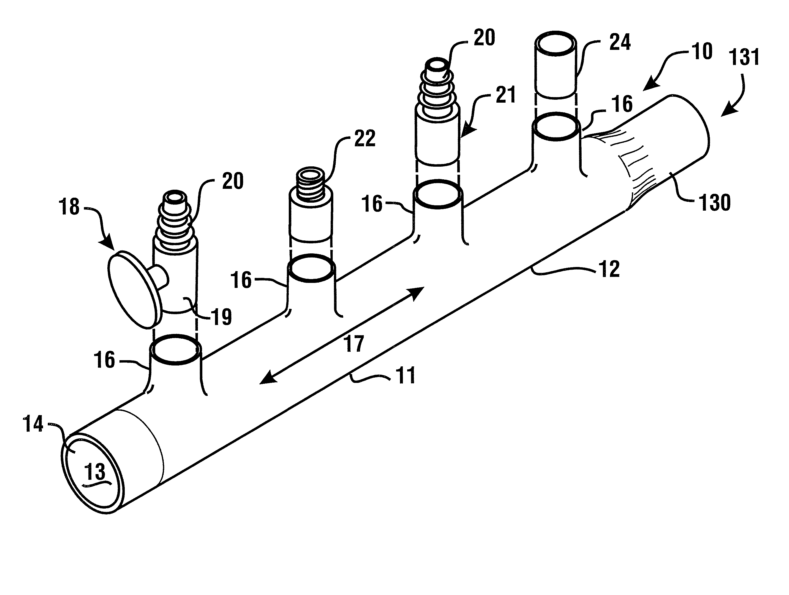
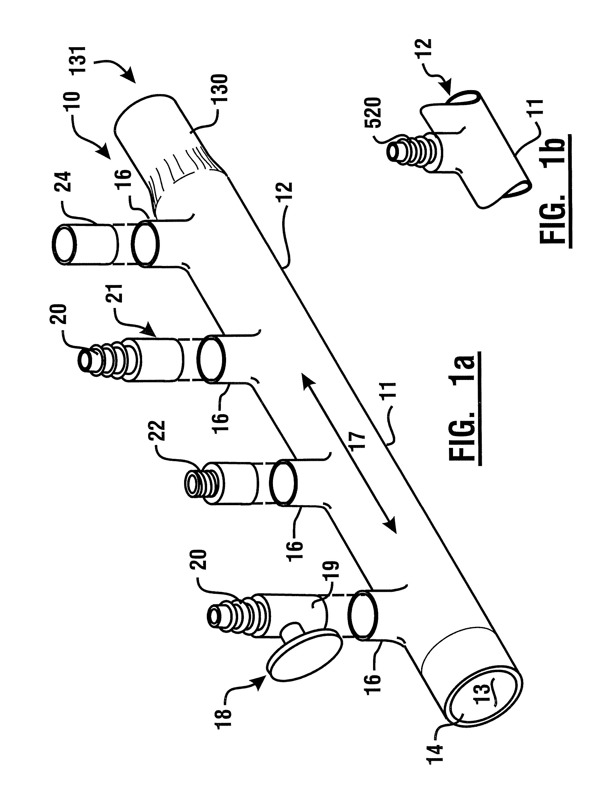
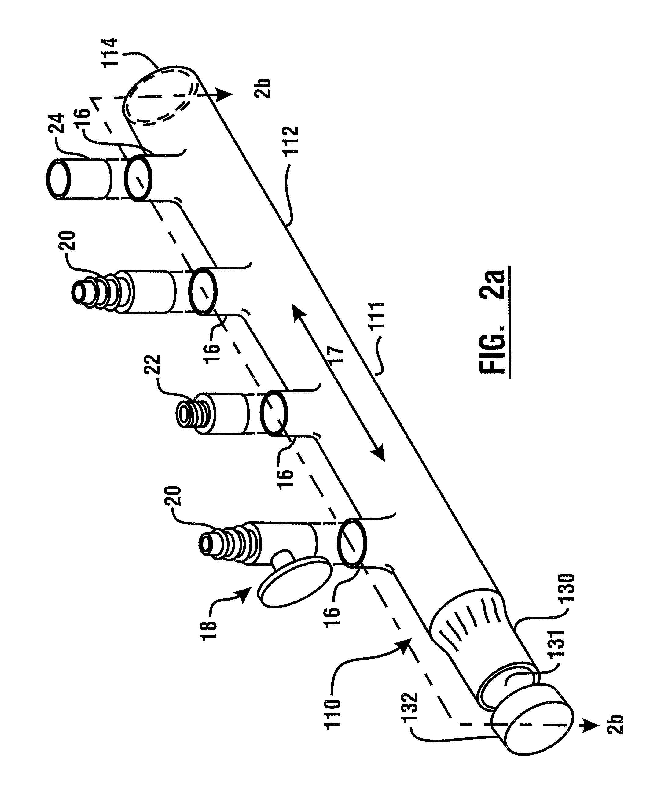
[0051]Referring now to the drawings, and particularly to FIG. 1a, there is shown therein a perspective view of an exemplary manifold system 10. In this exemplary embodiment, a manifold or distributor 12, is comprised of molded plastic material. In an exemplary embodiment, the manifold is comprised of a unitary molded CPVC manifold. Of course in other embodiments, other materials may be used. The manifold bounds a chamber 11 which defines an interior volume 13 of the manifold. The exemplary manifold further includes an entry port 14 and a plurality of liquid outlet ports 16, which are alternatively referred to herein as sockets. In an exemplary embodiment, the entry port may be configured to accept a standard copper tube size (CTS) outside diameter conduit therein. For example, in an exemplary embodiment the entry port 14 may be configured in the manner of a molded one inch CTS female coupling.

[0052]In the exemplary embodiment, the sockets 16 may be sized to accept standard CTS sized...


PUM


Abstract

A system for distributing water within a building operates to distribute water from a pressurized water supply source to devices that receive water, such as faucets, toilets, showers, sprinklers, and hot water heating devices. The system includes at least one manifold which may be of unitary molded plastic construction and comprised of chlorinated polyvinyl chloride (CPVC). The manifold includes an entry port and a plurality of outlet ports which are also referred to as sockets. The sockets are configured to receive fitting inserts of various types that include water line connectors. The sockets are also configured to accept standard plastic water conduits therein in cemented relation. The water line connectors may include metallic connectors such as barbed fittings, which can be used to connect the manifold and crosslinked polyethylene (PEX) pipe in nonthreaded relation. Manifolds may be connected together to provide suitable distribution arrangements.

Description

CROSS REFERENCE TO RELATED APPLICATION[0001]This application claims benefit pursuant to 35 U.S.C. §119(e) of Provisional Application 60 / 917,328 filed May 11, 2007, the disclosure of which is incorporated by reference as if fully rewritten herein.TECHNICAL FIELD[0002]This invention relates to water distribution systems and methods for distributing water to devices within a building. Exemplary embodiments relate to manifolds and systems which distribute potable water, hot water for heating, or water based fluids for other purposes, to multiple devices that receive water or fluids within a building. More particularly, exemplary embodiments relate to manifolds which are comprised of chlorinated polyvinyl chloride (CPVC) and which are suitable for connection though fitting inserts to multiple types of fluid conduits. Exemplary fluid conduits may of the type joined using solvent cement or other nonthreaded connections, and which are suitable for enclosure within the confines of a wall or ...

Claims


Application Information

Patent Timeline
Patent Type & Authority Applications(United States)
IPC IPC(8): E03B1/00
CPCE03C1/023F24D3/1066F16L41/03Y10T137/0402Y10T137/85938F16L41/00F16L41/02F16L41/04
Inventor BOYHER, CHRISTOPHER P.CUSON, SCOTT L.MAHABIR, CARL M.ZOOK, CHRISTOPHER D.
Owner LUBRIZOL ADVANCED MATERIALS INC
Learn More