

Alternating current light emitting device
- Summary
- Abstract
- Description
- Claims
- Application Information
AI Technical Summary
Benefits of technology
Problems solved by technology
Method used
Image

Examples
first embodiment
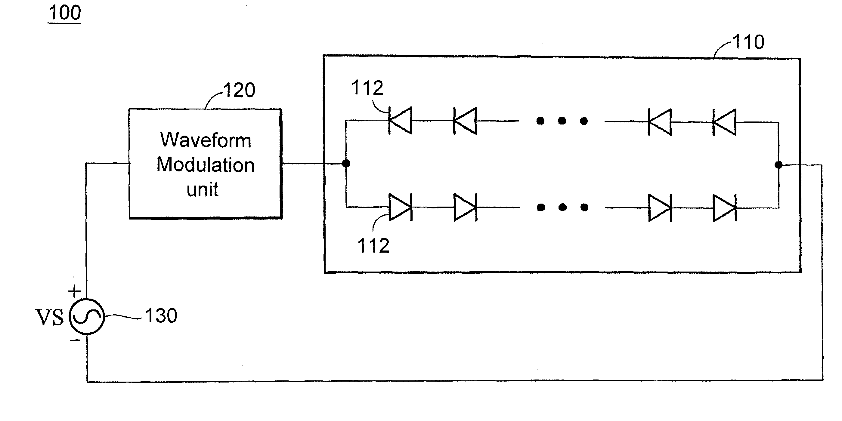
[0046]FIG. 2 is a schematic illustration showing an alternating current light emitting device 100 according to a first embodiment of the invention. Referring to FIG. 2, the alternating current light emitting device 100 includes an AC light emitting diode (LED) module 110 and a waveform modulation unit 120. The AC LED module 110 includes multiple micro-diodes 112, which are formed on a substrate (not shown) and are connected to form two strings (two sets) via wires on the substrate. In addition, the micro-diode 112 may be a lighting element having the operation power that may be adjusted according to different threshold voltage. For example, the micro-diode 112 may be, without limitation to, a micro light emitting diode (micro LED) or a micro laser diode (micro LD).
[0047]In general, the alternating current light emitting device is packaged into a package, which includes fluorescent powder capable of mixing the light outputted from the micro-diodes into other colors of light. In this ...
second embodiment
[0059]FIG. 7 is a schematic illustration showing an alternating current light emitting device 100′ according to a second embodiment of the invention. As shown in FIG. 7, the alternating current light emitting device 100′ is similar to the alternating current light emitting device 100 of FIG. 2 except that the waveform modulation unit 120 is omitted and a frequency modulation unit 140 is used to adjust the voltage frequency of the AC voltage source 130. The frequency modulation unit 140 adjusts the voltage frequency of the AC voltage source 130 from 60 Hz to fall within the range between 60 Hz and 100 Hz so that the user cannot feel the phenomenon of flicker through the effect of eye persistence of vision. Preferably, the frequency modulation unit 140 increases the voltage frequency of the AC voltage source 130 to fall within the range between 100 Hz and 60 KHz. More preferably, the frequency modulation unit 140 adjusts the voltage frequency of the AC voltage source 130 to fall withi...
third embodiment
[0061]FIG. 9 is a schematic illustration showing an alternating current light emitting device 100″ according to a third embodiment of the invention. Referring to FIG. 9, the alternating current light emitting device 100″ includes a modulation unit 150 for increasing the full width at half maximum (FWHM) of the input voltage VS provided by the AC voltage source 130, and increasing the voltage frequency of the AC voltage source 130 so as to increase the power factor of the alternating current light emitting device 100″ and improve the phenomenon of flicker sensed by the user simultaneously.
[0062]The waveform modulation unit 120 of FIG. 2 (or the frequency modulation unit 140 of FIG. 7 and the modulation unit 150 of FIG. 9) and the AC LED module 110 may be disposed on different chips or integrated within the same chip. In addition, the waveform modulation unit 120 of FIG. 2 (or the frequency modulation unit 140 of FIG. 7 and the modulation unit 150 of FIG. 9) may also be disposed outsi...
PUM
 Abstract
Description
Claims
Application Information