Motor Drive Device and Control Method Thereof

a technology of motor drive and control method, which is applied in the direction of motor control for motor oscillation damping, electric energy management, special data processing applications, etc., can solve the problems of increasing power loss, affecting the system efficiency and affecting the operation of the motor drive devi

Active Publication Date: 2009-06-25
DENSO CORP
View PDF20 Cites 22 Cited by
  • Summary
  • Abstract
  • Description
  • Claims
  • Application Information

AI Technical Summary

Benefits of technology

[0009]In view of the foregoing, an object of the present invention is to provide a motor drive device that can execute damp...

Problems solved by technology

As a result, the power loss occurring at the voltage-up converter increases to degrade the system efficiency of the motor drive device.
If this current becomes excessive, the switching element constitutin...

Method used


Image

  • Motor Drive Device and Control Method Thereof
  • Motor Drive Device and Control Method Thereof
  • Motor Drive Device and Control Method Thereof

Examples


first embodiment

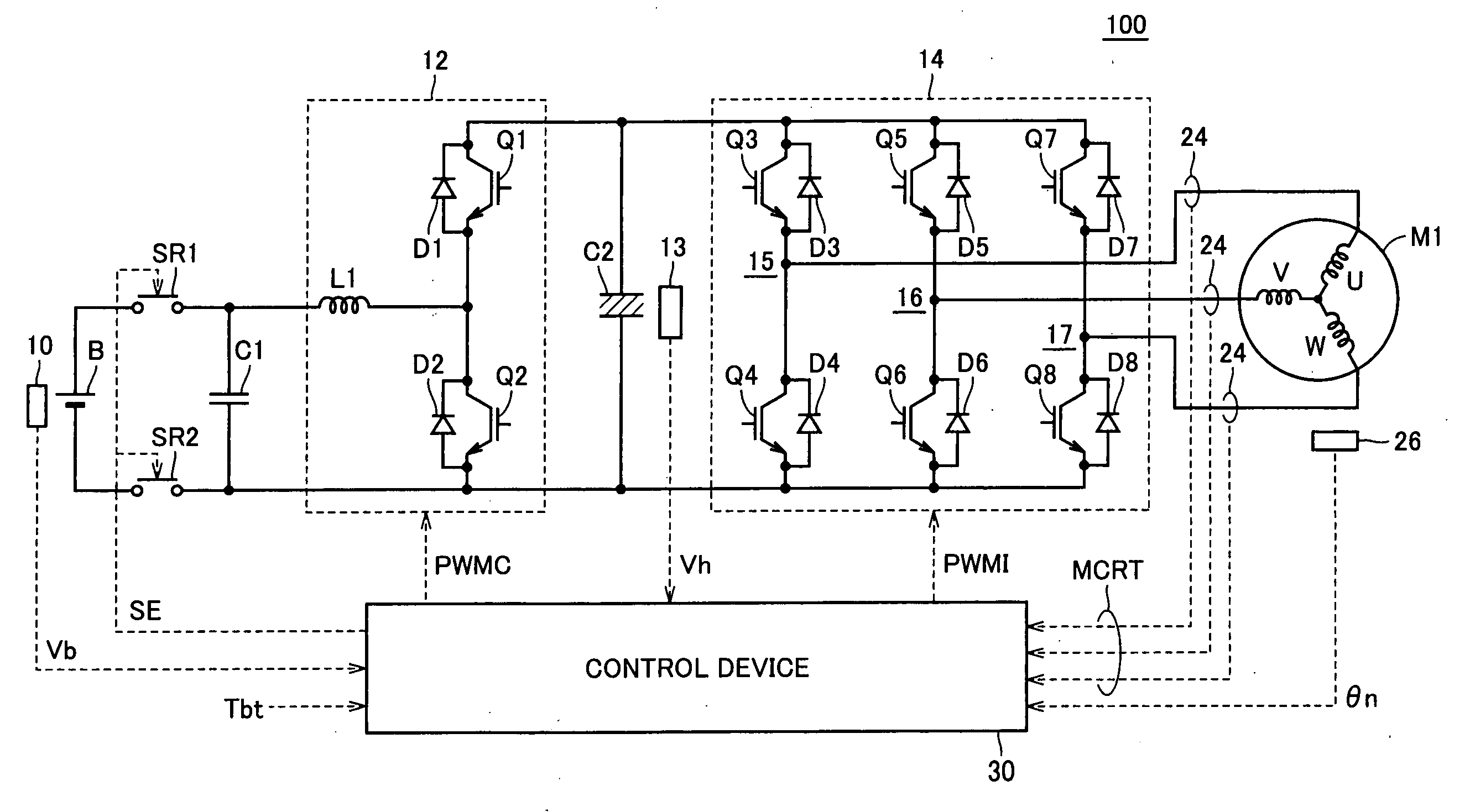
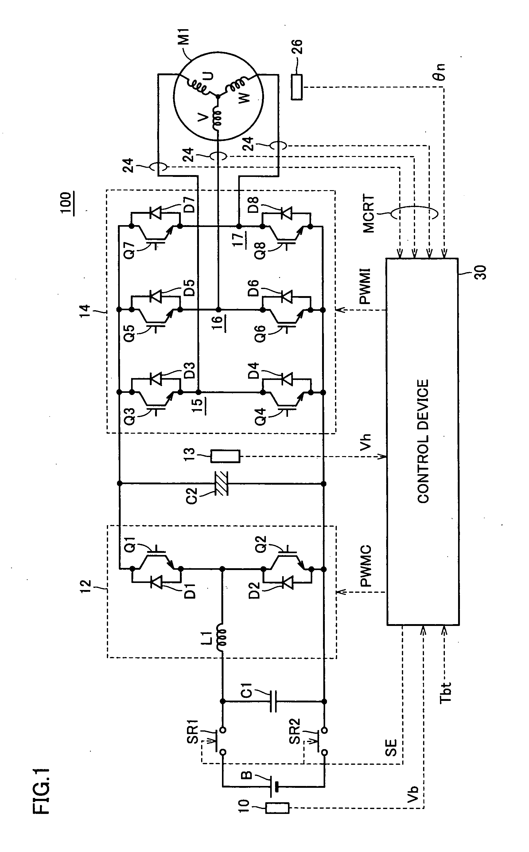
[0083]FIG. 1 is a schematic block diagram of a motor drive device according to a first embodiment of the present invention.

[0084]Referring to FIG. 1, a motor drive device 100 includes a DC power source B, voltage sensors 10 and 13, system relays SR1 and SR2, capacitors C1 and C2, a voltage-up converter 12, an inverter 14, a current sensor 24, a rotation position sensor 26, and a control device 30.

[0085]An AC motor M1 is a drive motor to generate torque for driving the driving wheel of a hybrid vehicle or electric vehicle. AC motor M1 is adapted to function as a power generator driven by an engine, and to operate as an electric motor for the engine to start, for example, the engine.

[0086]Voltage-up converter 12 includes a reactor L1, IGBT (Insulated Gate Bipolar Transistor) elements Q1 and Q2, and diodes D1 and D2.

[0087]Reactor L1 has one end connected to the power supply line of battery B, and the other end connected to the intermediate point between IGBT element Q1 and IGBT element...

second embodiment

[0151]In the previous first embodiment, torque command Tht at converter control circuit 302 is generated using damping torque Tcct fixed to damping torque upper limit value Tc_max, independent of inverter control circuit 301.

[0152]Although variation in voltage command Vht is suppressed by taking a fixed value for damping torque Tcct, a high voltage exceeding the level of the motor drive voltage required for damping control will be constantly output from voltage-up converter 12. This will increase the power loss of voltage-up converter 12 and also increase motor loss occurring at AC motor M1. Such increase in loss will become the cause of deteriorating fuel efficiency of the vehicle in which motor drive device 100 is incorporated.

[0153]In addition to damping control set forth above, motor drive device 100 controls the output torque of AC motor M1 such that the power balance of the entire device does not exceed the input / output limit of battery B. This is directed to preventing chargi...

third embodiment

[0175]Damping control is effective to suppress vehicle variation caused by torque pulsation when there is a sudden change in the torque command and / or motor revolution. If damping control is conducted uniformly even in the case where determination is made that effectiveness in damping control is relatively low, i.e. when torque pulsation is relatively low, voltage command Vht will constantly be raised corresponding to the damping torque upper limit value, leading to the problem that power loss of voltage-up converter 12 is increased unfavorably.

[0176]In view of the foregoing, the third embodiment of the present invention is configured to determine the effectiveness / ineffectiveness of damping control and suspend damping control, when determination is made that damping control is not effective, to prevent voltage command Vht from being increased corresponding to damping torque upper limit value Tc_max.

[0177]FIG. 11 is a diagram to describe voltage command Vht according to the third em...


PUM


Abstract

A torque command (Tht) used in the calculation of a voltage command (Vht) of a voltage-up converter is generated by adding an upper limit value value (Tc_max) of damping control that can be set by a motor drive device with a target drive torque (Tbt). Accordingly, the torque command (Tht) exhibits a waveform absent of variation, differing from a torque command (Tcmd) that is generated by adding damping torque generated based on revolution count variation component with the target drive torque (Tbt). Therefore, the voltage command (Vht) calculated based on the torque command (Tht) exhibits a waveform absent of variation. Accordingly, increase in current passing through the voltage-up converter caused by variation in the voltage command (Vht) can be suppressed. As a result, power loss at the voltage-up converter is reduced and operation of the motor at high efficiency can be realized. Further, the voltage-up converter can be protected from element fracture.

Description

TECHNICAL FIELD[0001]The present invention relates to a motor drive device and a control method thereof. Particularly, the present invention relates to a motor drive device with a damping control function of output torque, and a method of controlling the motor drive device.BACKGROUND ART[0002]Recently, attention is focused on hybrid vehicles and electric vehicles as vehicles taking into account environmental issues. A hybrid vehicle includes, in addition to a conventional engine, a DC (direct current) power source, an inverter, and a motor driven by the inverter as the power source. In addition to achieving the power source by driving the engine, the DC voltage from the DC power source is converted into AC (alternating current) voltage by the inverter, and the converted AC voltage is used to rotate the motor to achieve power.[0003]An electric vehicle includes a DC power source, an inverter, and a motor driven by the inverter as the power source.[0004]A motor drive device incorporate...

Claims


Application Information

Patent Timeline
IPC IPC(8): H02P6/10H02P27/00H02P29/00H02P29/68
CPCB60L15/20B60L2210/14B60L2210/20H02P6/10Y02T10/7275Y02T10/644Y02T10/7225Y02T10/725H02P23/04Y02T10/64Y02T10/72Y02T10/62B60L15/02
Inventor YAMADA, KENJIOYAMA, SHUNSUKEITAGAKI, KENJISUGAI, SHINICHIOCHIAI, KIYOE
Owner DENSO CORP
Why Eureka
Try Eureka