Virtual Moving Air Gap For An Axial Flux Permanent Magnet Motor With Dual Stators

a permanent magnet motor and virtual moving air gap technology, applied in the direction of motor/generator/converter stopper, dynamo-electric converter control, ac motor stopper, etc., can solve the problems of limitation of reducing the efficiency of the motor, at the expense of low end torque, etc., to increase the maximum speed of the motor and reduce the back emf

Inactive Publication Date: 2009-06-25
THE TIMKEN CO
View PDF10 Cites 43 Cited by
  • Summary
  • Abstract
  • Description
  • Claims
  • Application Information

AI Technical Summary

Problems solved by technology

If a high top speed is required, this must come at the expense of low end torque.
This method requires complex mechanical assemblies that allow the rotor and stator to change position with respect to one another.
This has the obvious limitation of reducing the efficiency of the motor.
In many applications, such as an electrically-powered automobile, this is unacceptable.

Method used


Image

  • Virtual Moving Air Gap For An Axial Flux Permanent Magnet Motor With Dual Stators
  • Virtual Moving Air Gap For An Axial Flux Permanent Magnet Motor With Dual Stators
  • Virtual Moving Air Gap For An Axial Flux Permanent Magnet Motor With Dual Stators

Examples


first embodiment

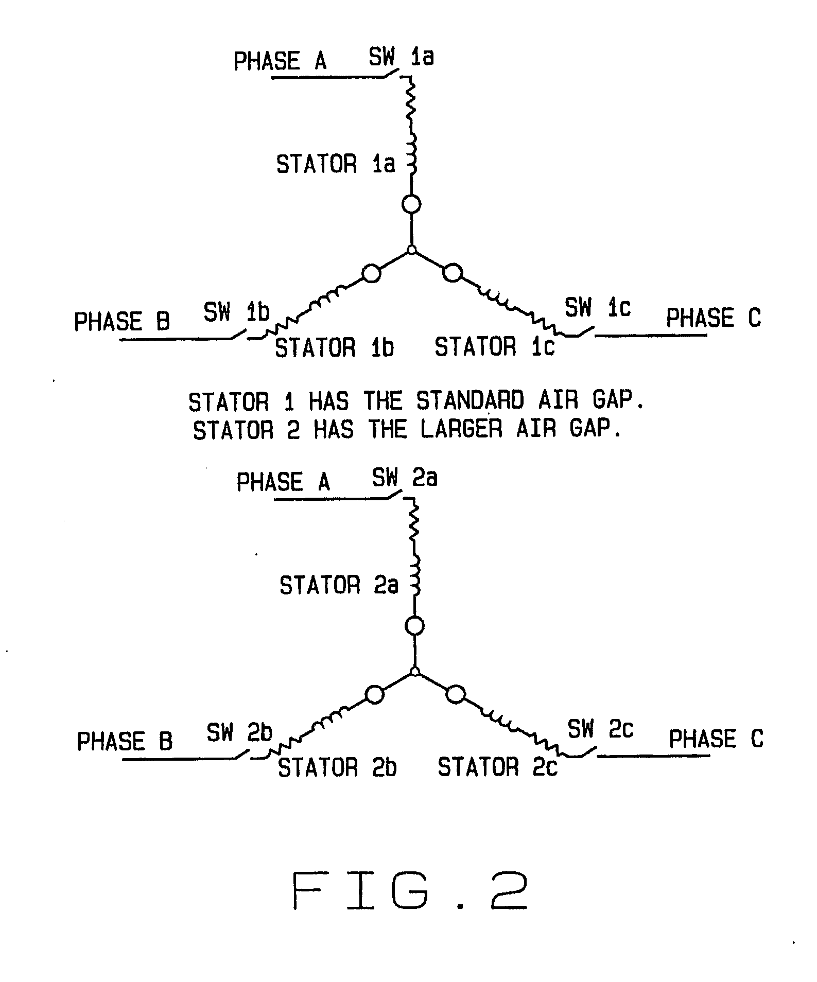
[0027]In the first embodiment, the stators 40 and 140 are wired individually to the drive in a parallel configuration with a set of power electronic switches in series with each stator 40 and 140 as shown in FIG. 2.

[0028]As shown in FIG. 2, the SW1 and SW2 switches are always in opposite states. They can never be turned on at the same time. During the motor operation the SW1 and SW2 switches will be switched at high frequency in a pulse width modulation scheme. Thereby increasing the duty cycle to one will cause an equal decrease in duty cycle to the other.

[0029]The motor will start out with SW1 conducting 100% of the time, and SW2 conducting 0% of the time. This effect is that stator 140, with the larger air gap, is not even in the circuit. The torque and BEMF constants will be that of stator 40 only.

[0030]As the need for a wider speed range increases and the need to for low speed torque decreases, the duty cycle is changed such that SW2 is conducting for a greater percentage of th...

third embodiment

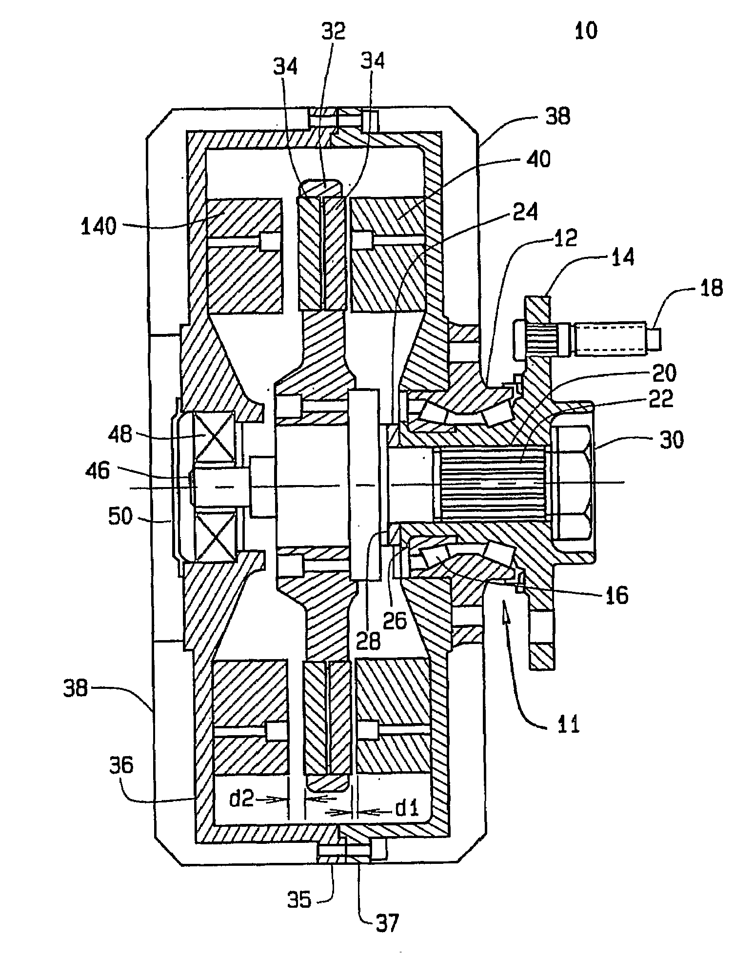
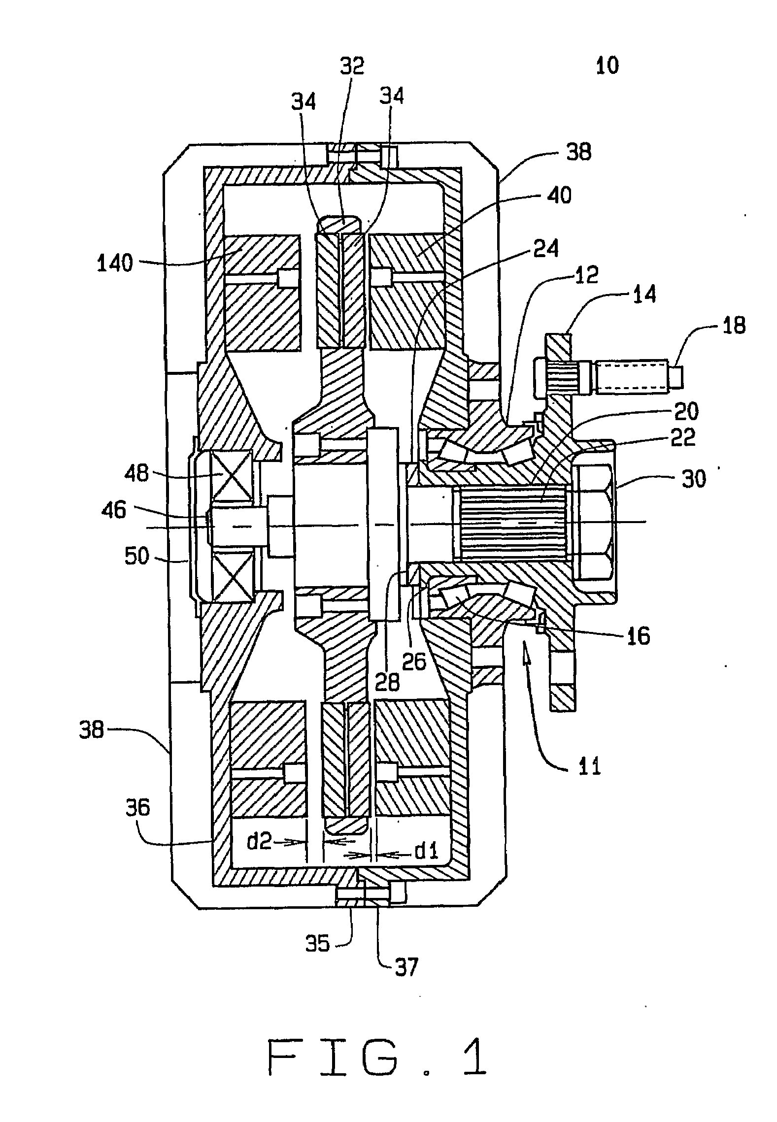
[0044]In the invention, the stators 40 and 140 are wired in series with power electronic switches to turn off and bypass one of the stators, as shown in FIG. 3.

[0045]In this method, each stator is wound with the maximum torque constant and BEMF constant that will yield full motor torque at the continuous rated current, assuming a standard air gap distance. This maximum winding will be done based on a half motor view. For example; if the maximum torque that can be produced by the machine is 700 NM, then each stator will be wound to produce 350 NM at rated current with a standard air gap. This will likely cause the BEMF constant to be high enough that desired full speed could not be obtained due to the limited bus voltage.

[0046]However, in this embodiment, one stator 40 is positioned with a standard air gap. The other stator 140 is positioned at an extended air gap. The BEMF constant of the stator 140 with the extended air gap is reduced by some percentage based on the distance of the...


PUM


Abstract

An axial flux electric motor comprising a rotor and a first and second stator. The first and second stators have a first and second air gap located between the first and second stators and the rotor, respectively, and the second air gap is greater than the first gap. In one embodiment, the coils of the first stator and the coils of the second stator are in parallel. The motor further comprises switches which alternatingly energize the coils of the first stator and of the second stator based upon required torque and required speed of the motor. In a second embodiment, the coils of the first stator and the coils of the second stator are in series and the motor further comprises switches which selectively bypass the coils of the second stator in order to reduce the back EMF of the motor and increase the maximum speed of the motor at a given input voltage.

Description

RELATED APPLICATIONS[0001]This application claims priority to U.S. Patent Application No. 60 / 762,438 filed Jan. 26, 2006, U.S. Patent Application No. 60 / 788,934 filed Apr. 4, 2006, U.S. Patent Application No. 60 / 793,121 filed Apr. 19, 2006, and U.S. Patent Application No. 60 / 747,878 filed May 22, 2006. The contents of said applications are incorporated herein by reference.TECHNICAL FIELD[0002]The invention relates to electric motors. More specifically, the invention relates to a dual stator axial flux motor wherein the stators have air gaps that are unequal.BACKGROUND ART[0003]Permanent magnet motors have a trade off between having high torque at low speed and having a high speed range. Specifically, if the motor is built such that large amounts of low end torque are produced, the top speed of the motor is reduced. If a high top speed is required, this must come at the expense of low end torque.[0004]For applications such as use in an electrically-powered automobile, it is desirable...

Claims


Application Information

Patent Timeline
Patent Type & Authority Applications(United States)
IPC IPC(8): H02P25/18H02K21/24H02K16/04
CPCH02K16/04H02P25/18H02K21/24H02P5/46
Inventor MULARCIK, BRADLEY S.
Owner THE TIMKEN CO
Why Eureka
Try Eureka