Living Eye Judging Method and Living Eye Judging Device

a living eye and iris technology, applied in the field of living eye judging, can solve the problems of false authentication of iris photographs or counterfeit eyes, and achieve the effects of high luminance in the pupil region, easy to perform, and large luminance differen

Active Publication Date: 2009-06-25
PANASONIC INTELLECTUAL PROPERTY CORP OF AMERICA
View PDF15 Cites 12 Cited by
  • Summary
  • Abstract
  • Description
  • Claims
  • Application Information

AI Technical Summary

Benefits of technology

[0017]According to the present invention, the pupil region in an image obtained by shooting a living eye with illumination coaxial with the optical axis of the camera has high luminance by the retinal reflex. On the other hand, no retinal reflex is caused in a photograph, a printed imaged and a counterfeit eye, so that the luminance in the pupil region is not so high as that in a living eye. In this connection, judgment as to whether an eye included in an image is a living eye or not can be performed easily based on the luminance of the pupil region in the image.
[0019]In this invention, in a case of a living eye, the luminance in the pupil region is high because of the retinal reflex in the first image obtained by shooting the subject with illumination coaxial with the optical axis of the camera and the luminance in the pupil region is low in the second image obtained by shooting the subject with illumination of which optical axis is different from the optical axis of the camera. In short, a large difference is present in the pupil region between the first and second images. On the other hand, in a photograph, a printed image and a counterfeit eye, not so large difference in luminance is present between the pupil regions of the first and second images as in the living eye. Accordingly, the judgment as to whether the eyes included in the images are a living eye or not can be performed easily based on the luminance of the pupil regions in the images. Further, no luminance difference is present between the first and second images even in the case using a photograph and a printed image including an eye upon the retinal reflex, and therefore, accurate judgment is attained.

Problems solved by technology

In personal authentication using iris images, there is a possibility of false authentication of a photograph of an iris or a counterfeit eye.

Method used


Image

  • Living Eye Judging Method and Living Eye Judging Device
  • Living Eye Judging Method and Living Eye Judging Device
  • Living Eye Judging Method and Living Eye Judging Device

Examples


first embodiment

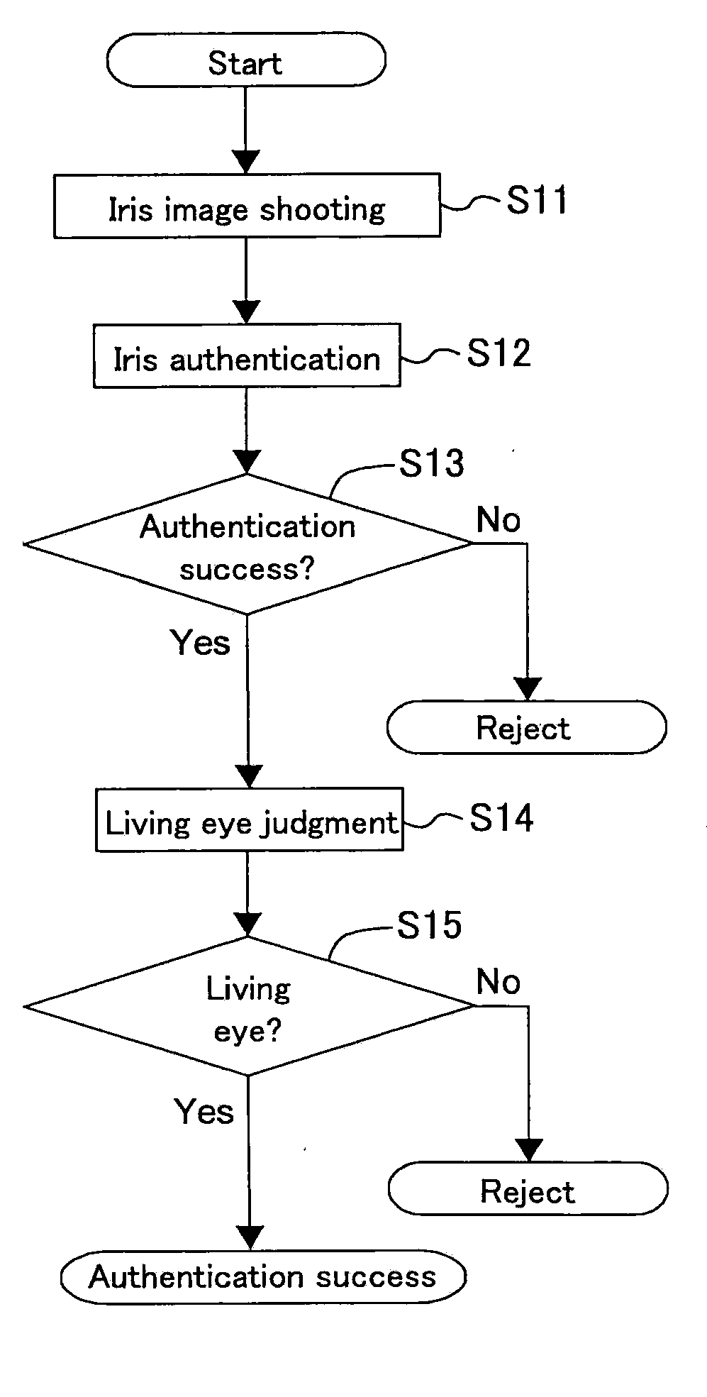
[0055]FIG. 4 is a flowchart showing an iris authentication method according to the first embodiment of the present invention. The flow of FIG. 4 includes steps S14 and S15 of performing living eye judgment.

[0056]FIG. 5 shows one example of the constitution of an iris authentication device according to the present embodiment. In FIG. 5, a shooting device 10 is provided with a camera 11 for shooting an eye EY (a subject) of a person to be shot, an illumination 12 and a half mirror 13. Light emitted from the illumination 12 is reflected on the half mirror 13 to illuminate the eye EY. The camera 11 captures an image of the eye EY through the half mirror 13 when the subject is illuminated by the illumination 12. At this time, the optical axis of the camera 11 is coaxial with that of the illumination 12 (coaxial incident illumination). In this way, the illumination 12 and the half mirror 13 composes illumination means 19. An image processing section 15 is provided with an iris authenticat...

second embodiment

[0095]An iris authentication method according to the second embodiment of the present invention is the same in the basic processing flow as in the first embodiment. It is the difference that living eye judgment is performed in such a manner that a second image is obtained by shooting a subject with illumination of which optical axis is different from the optical axis of a camera separately from a first image obtained by shooting the subject with illumination coaxial with the optical axis of the camera and the first and second images are used.

[0096]FIG. 17 shows one example of the constitution of an iris authentication device according to the present embodiment, wherein the same reference numerals as in FIG. 5 are assigned to the common constitutional elements in FIG. 5. Different from the shooting device 10 in FIG. 5, a shooting device 20 in FIG. 17 is provided with an illumination 21 in addition to the illumination 12. The illumination 21 illuminates the eye EY of a person to be sh...

third embodiment

[0116]The basic processing flow of an iris authentication method according to the third embodiment of the present invention is the same as that in the first embodiment. It is the difference therefrom that a plurality of images are obtained in shooting of a subject with the illumination coaxial with the optical axis of the camera and living eye judgment is performed using the plural images.

[0117]The device in FIG. 5 is used as an iris authentication device according to the present embodiment, likewise the first embodiment. The constitutional elements in FIG. 5 are the same as those in the first embodiment, and the description thereof is omitted.

[0118]The processing in the present embodiment will be described with reference to the flow of FIG. 4. Of course, the living eye judgment may be performed before the iris authentication as shown in FIG. 7, or may be performed in parallel to the iris authentication.

[0119]First, in the step S11, the shooting device 10 shoots a plurality of iris ...


PUM


Abstract

An eye (EY) of a person to be shot is illuminated coaxially with the optical axis of a camera (11), and then, is shot. At this time, a retinal reflex is caused and the luminance in the pupil region becomes high if the eye (EY) is a living eye. A living eye judgment section (17) judges whether an eye included in the image is a living eye is performed based on the luminance in the pupil region of the image captured by the camera (11).

Description

CROSS-REFERENCE TO RELATED APPLICATION[0001]This application is a continuation of U.S. patent application Ser. No. 10 / 540,060 filed on Jun. 22, 2005. The entire disclosure of the above application is incorporated herein by reference.TECHNICAL FIELD[0002]The present invention relates to generally called a living eye judgment for judging whether an eye included in an image is a living eye or not for preventing false authentication of one which is not a living eye, for example, in iris authentication.BACKGROUND ART[0003]In recent years, a personal authentication technique utilizing iris images has been started to be used for entrance / exit management in a restricted building, bank ATMs (Automated Teller Machines), PC login applications, and the like. Especially, the method disclosed in Patent Document 1 has already gone commercial in all over the world and is becoming a de facto standard method.[0004]In the method disclosed in Patent Document 1, an iris region is cut out from an image o...

Claims


Application Information

Patent Timeline
Patent Type & Authority Applications(United States)
IPC IPC(8): G06K9/00A61B3/11A61B3/12G06T7/00
CPCA61B3/112G06T2207/30041G06K9/00597A61B3/12G06V40/18
Inventor KONDO, KENJIAZUMA, TAKEO
Owner PANASONIC INTELLECTUAL PROPERTY CORP OF AMERICA
Why Eureka
Try Eureka