Thermal reactor with improved gas flow distribution

a technology of gas flow and reactor, which is applied in the direction of disinfection, lighting and heating apparatus, furnaces, etc., can solve the problems of reducing non-uniformity, reducing the non-uniformity of gas distribution in the conventional chamber, and not being able to rotate alone, so as to improve the gas distribution

Active Publication Date: 2009-06-25
APPLIED MATERIALS INC
View PDF8 Cites 29 Cited by
  • Summary
  • Abstract
  • Description
  • Claims
  • Application Information

AI Technical Summary

Benefits of technology

[0009]The present invention provides methods and apparatus for performing a thermal process. More particularly, embodiments of the present invention provide apparatus and method for improving gas distribution during thermal processing.

Problems solved by technology

Gas distribution in a conventional chamber is not uniform across the chamber.
Although, continuous rotation of the substrate may reduce the non-uniformity of gas distribution, the rotation alone may not be enough as the requirement for uniformity increases.

Method used


Image

  • Thermal reactor with improved gas flow distribution
  • Thermal reactor with improved gas flow distribution
  • Thermal reactor with improved gas flow distribution

Examples


Embodiment Construction

[0022]The present invention provides methods and apparatus for thermally processing semiconductor substrates. Thermal processing chambers of the present invention comprise an exhaust assembly configured to extend a processing volume along a direction of a gas flow to improve gas distribution uniformity. Embodiments of the present invention further comprise a side injection assembly configured to provide a side flow to improve edge processing. Additionally, thermal processing chambers of the present invention comprise an injection cartridge having two or more input to improve flow uniformity across a length of an injection port.

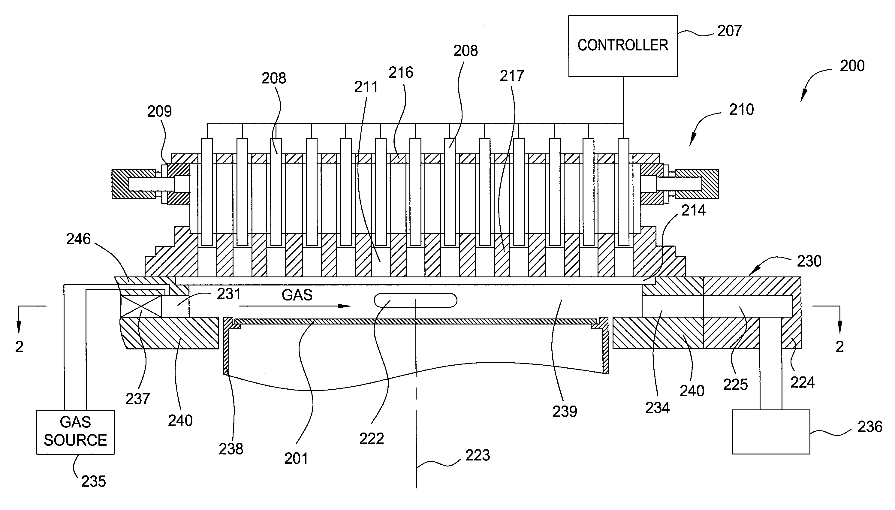
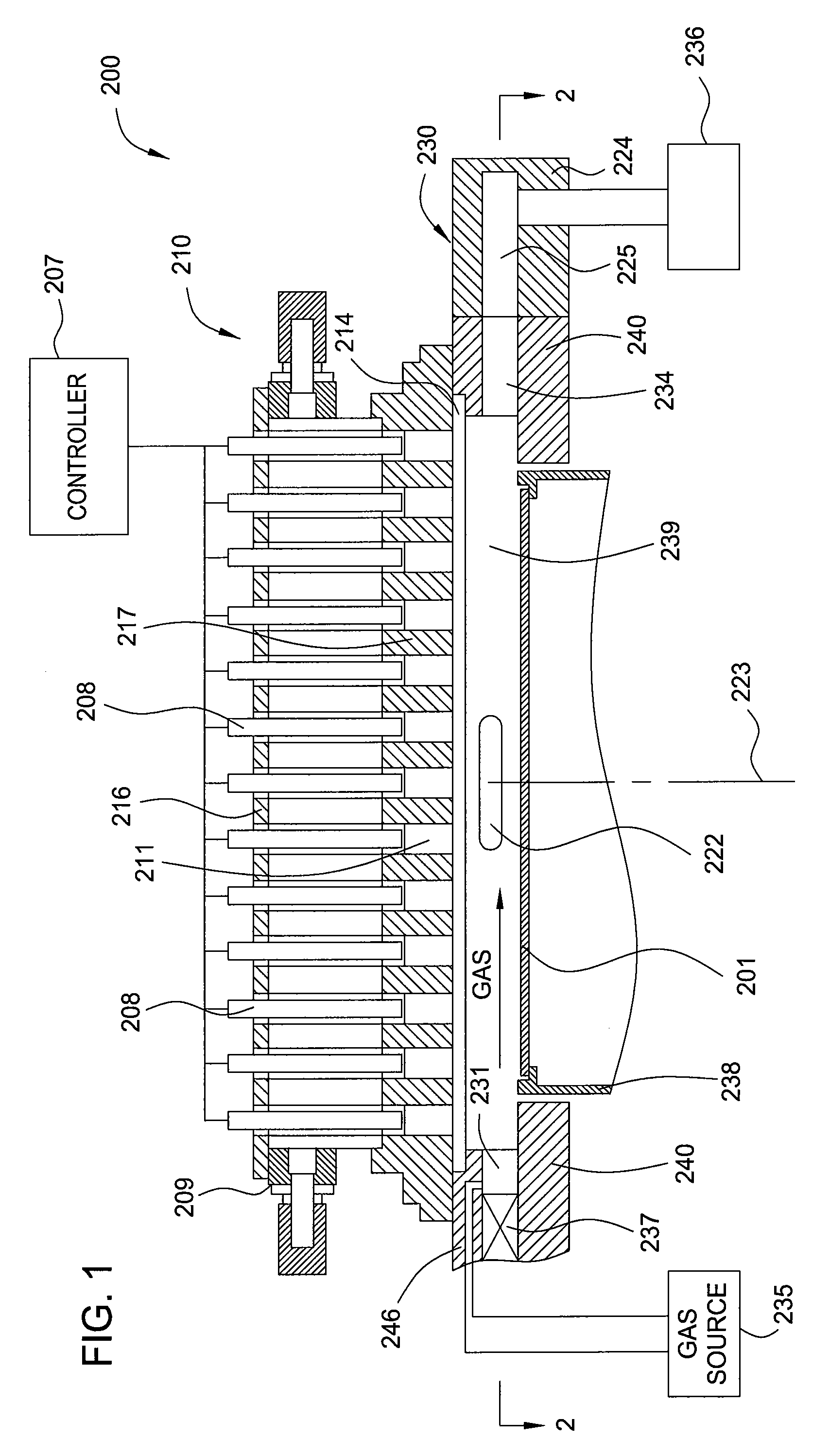
[0023]FIG. 1 is a schematic sectional side view of a thermal processing chamber 200 in accordance with one embodiment of the present invention.

[0024]The thermal processing chamber 200 generally comprises a lamp assembly 210, a chamber assembly 230 defining a processing volume 239, and a substrate support 238 disposed in the processing volume 239.

[0025]The lamp...


PUM

PropertyMeasurementUnit
temperatureaaaaaaaaaa
volumeaaaaaaaaaa
flow rateaaaaaaaaaa

Abstract

Embodiments of the present invention provide apparatus and method for improving gas distribution during thermal processing. One embodiment of the present invention provides an apparatus for processing a substrate comprising a chamber body defining a processing volume, a substrate support disposed in the processing volume, wherein the substrate support is configured to support and rotate the substrate, a gas inlet assembly coupled to an inlet of the chamber body and configured to provide a first gas flow to the processing volume, and an exhaust assembly coupled to an outlet of the chamber body, wherein the gas inlet assembly and the exhaust assembly are disposed on opposite sides of the chamber body, and the exhaust assembly defines an exhaust volume configured to extend the processing volume.

Description

CROSS-REFERENCE TO RELATED APPLICATION[0001]This patent application Claims Priority to U.S. Provisional Patent Application Ser. No. 61 / 015,435 filed Dec. 20, 2007 (Attorney Docket No. APPM / 11945L), which is incorporated by reference in its entirety.BACKGROUND OF THE INVENTION[0002]1. Field of the Invention[0003]The present invention relates generally to a semiconductor processing tool and, more specifically, to a thermal reactor with improved gas flow distribution.[0004]2. Description of the Related Art[0005]Rapid thermal processing, commonly referred to as ‘RTP’, subjects a substrate to a very brief, intense burst of heat that can go from room temperature to about 1000° C. in seconds. RTP technology is used to change the characteristics of a deposited film or crystal lattice. RTP generally includes processes such as annealing, silicidation and oxidation of a substrate surface.[0006]Generally, an RTP chamber includes a radiant heat source or lamp, a chamber body, a substrate support...

Claims


Application Information

Patent Timeline
Patent Type & Authority Applications(United States)
IPC IPC(8): H01L21/263A61L2/04
CPCH01L21/67017F27D7/06H01L21/67115H01L21/67098
Inventor TAM, NORMANYOKOTA, YOSHITAKATJANDRA, AGUSNAVASCA, ROBERTBEHDJAT, MEDHRANRAMAMURTHY, SUNDARSANGAM, KEDARNATHLERNER, ALEXANDER N.
Owner APPLIED MATERIALS INC
Why Eureka
Try Eureka