Ceiling fan

A ceiling fan and fan blade technology, applied in the field of electric ceiling fans and their efficiency, can solve problems such as air flow distribution and fan reduction

Inactive Publication Date: 2008-03-12
HUNTER FAN
View PDF7 Cites 0 Cited by
  • Summary
  • Abstract
  • Description
  • Claims
  • Application Information

AI Technical Summary

Problems solved by technology

[0007] Another longstanding problem with ceiling fans is airflow distribution
However, this only comes at the cost of drastically reducing airflow directly under the fan

Method used


Image

  • Ceiling fan
  • Ceiling fan
  • Ceiling fan

Examples


Embodiment Construction

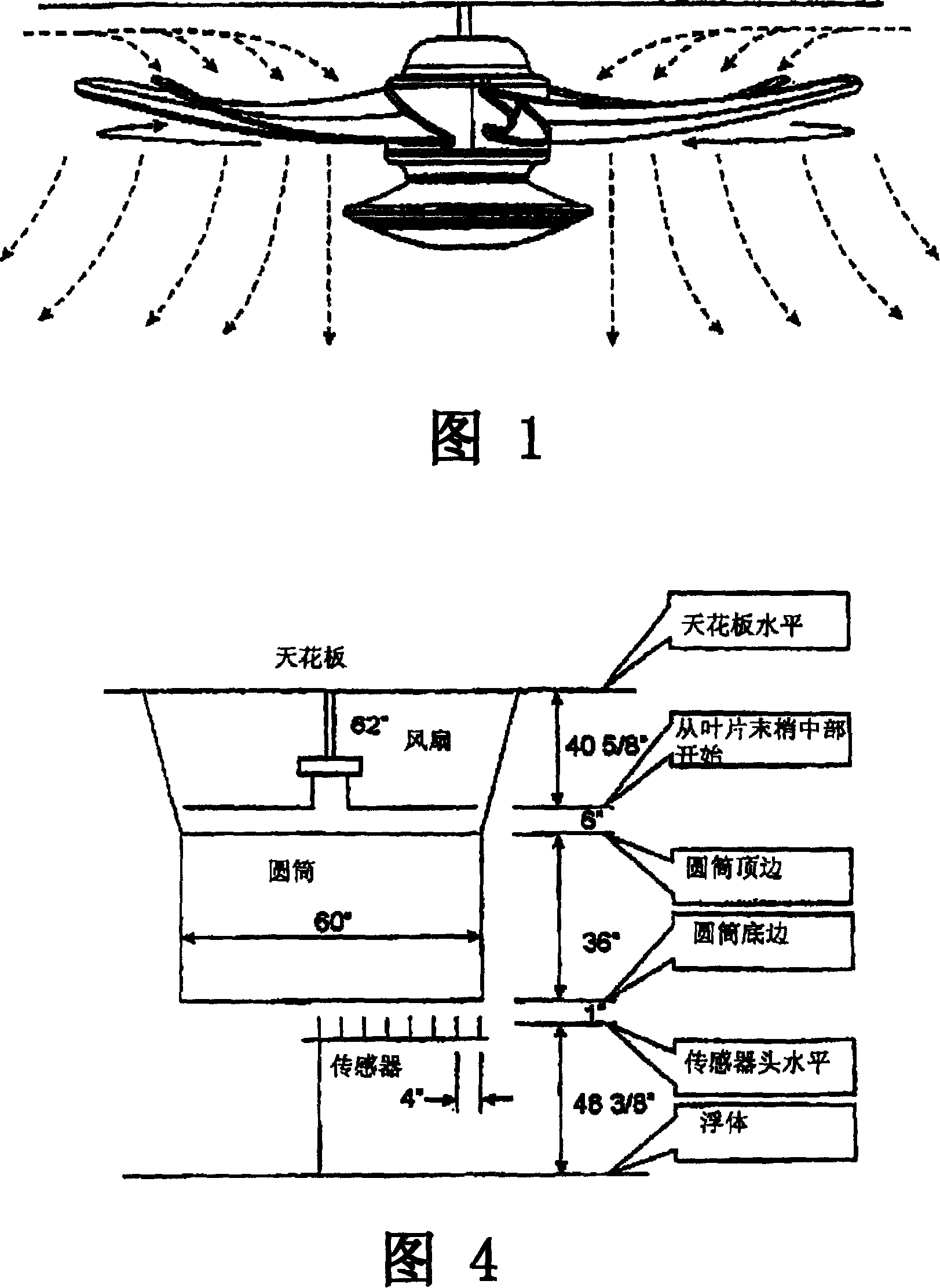
[0019] The fan blade technology disclosed in US Patent Application No. 6,039,541 follows the assumption that all airflow entering the fan blades is from a direction perpendicular to the plane of rotation of the blades. Furthermore, as is used in aircraft propeller theory, it is also assumed that the airflow flows at a constant velocity from the root of the blade to the tip of the blade. Utilizing this assumption, the twist angle from the root end to the tip is assumed to be a certain value when designing the blade.

[0020] The purpose of twisting the blades is an attempt to optimize the relative angle of attack of the airflow direction with respect to the blade surface. This is done to ensure that the blade operates at an optimal angle of attack from its root to its tip. This change in angle is to accommodate the fact that the tip of the blade is moving faster than the diameter of the root of the blade, and this increase in speed changes the relative airflow direction over t...


PUM


Abstract

Ceiling fan energy consumption efficiency is enhanced with fan blades that have an angle attack that decreases from root end to tip end at higher rates of decrease nearer their tip ends than at their root ends. Air flow distribution is enhanced with at least a portion of the blades having a dihedral that continuously increases.

Description

[0001] Related application reference [0002] This application is a Continuing Application Serial No. 10 / 194,699 filed July 11,2002. technical field [0003] This invention relates generally to ceiling fans, and more particularly to electric ceiling fans and their efficiency. Background technique [0004] Ceiling fans driven by electric motors have been used for many years to circulate air. Such ceiling fans typically have an electric motor located in the housing, which is secured to an upright pole to rotate the fan blades about the upright pole. Such fan blades are traditionally flat and oriented with a slope, or pitch, so that as they rotate through the air they form an angle of attack relative to the air mass, which drives the air downward. [0005] When the fan blades, which extend radially from the axis of rotation, rotate, their tips travel a much longer path than their roots for a certain period of time. Therefore the velocity at the tip of the fan blade is much g...

Claims


Application Information

Patent Timeline
Patent Type & Authority Patents(China)
IPC IPC(8): F04D29/38
Inventor G·M·伯德
Owner HUNTER FAN
Why Eureka
Try Eureka