Auxiliary sub-cooler for refrigerated dispenser

Active Publication Date: 2009-07-02
MARMON FOODSERVICE TECH INC
View PDF22 Cites 4 Cited by
  • Summary
  • Abstract
  • Description
  • Claims
  • Application Information

AI Technical Summary

Benefits of technology

[0005]The present invention provides an apparatus and method for solving the above difficulties, while further increasing the refrigeration efficiency and cooling capacity of the unit or dispenser, be it ice, beverage, frozen carbonated beverage (FCB), or frozen uncarbonated beverage (FUB) dispensers. Instead of hot gas, in the present invention, warm liquid refrigerant after the condenser is used. This has the advantage of lower energy state (lower enthalpy and temperature). Almost all of the heat will be dissipated to keep the foam pack bottom warm to prevent condensation. Thus, the heat will not reach the evaporator coils, but instead, will also further cool the liquid refrigerant before its expansion to increase cooling capacity. The present invention comprises a freeze chamber (including its surrounding refrigeration lines), enclosed in insulation, surrounded by a protective metal

Problems solved by technology

While such foam pack freeze chambers are successful, they have had the disadvantage of causing moisture and humidity to collect on the cold foam pack, and particularly its protective outer metal surface.
Thus, humidity due to the low temperature may collect into droplets which can fall from the foam pack upon other components, such as electrical components, causing damage to such components, and can require additional maintenance.
The condensate can also cause corrosion and l

Method used


Image

  • Auxiliary sub-cooler for refrigerated dispenser
  • Auxiliary sub-cooler for refrigerated dispenser
  • Auxiliary sub-cooler for refrigerated dispenser

Examples


Embodiment Construction

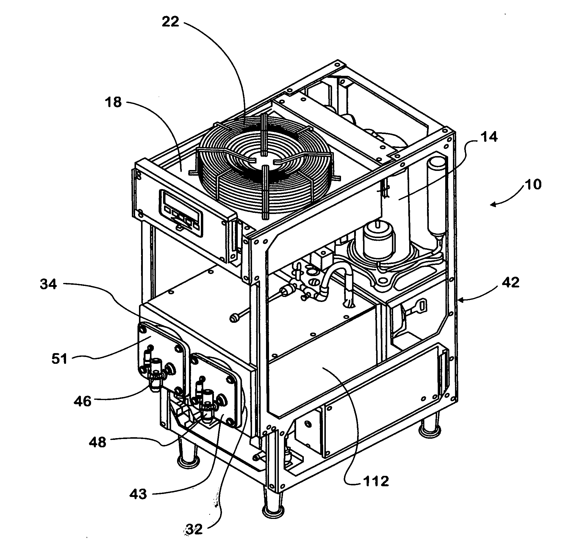
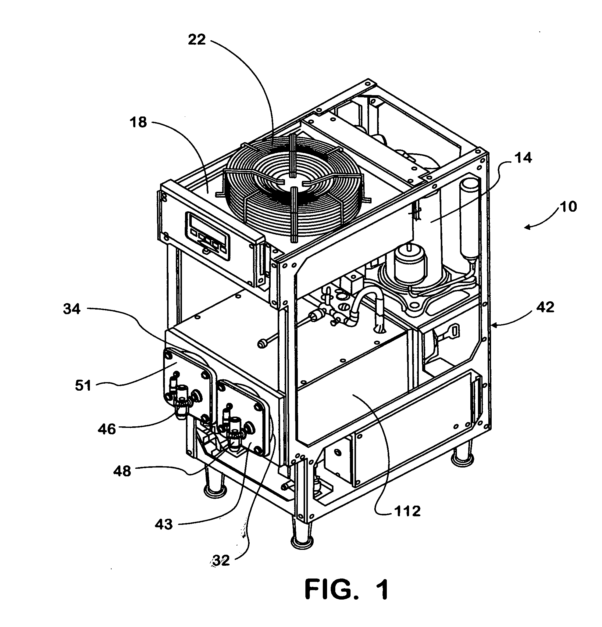
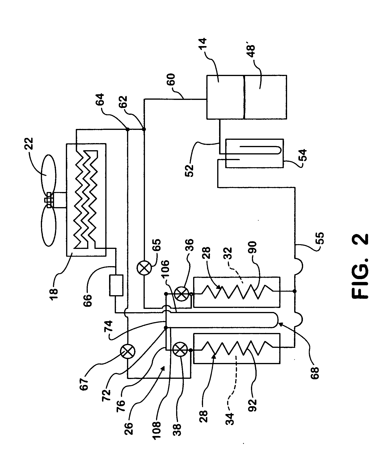
[0022]Referring to FIG. 1, a dispenser 10, in this instance a frozen carbonated beverage (FCB) dispenser, is shown. As is shown in FIG. 1 and also FIG. 2, the dispenser 10 herein includes refrigeration components, namely a compressor 14, a condenser 18, cooling fan 22 for the same, expansion means 26, an evaporator 28 in the form of two FCB freeze chambers 32 and 34. It should be understood that few (one) or three, four or more freeze chambers could be provided in the dispenser. See FIG. 10 table for sizing the various components for units with from two to four freeze chambers. While having multiple freeze chambers (or evaporators) there is usually only one compressor and condenser and auxiliary sub-cooler in each system. In this instance as more clearly shown in FIG. 2, there are separate expansion means in the form of expansion valves 36 and 38, one for each evaporator freeze chamber 32 and 34. It should be understood that other forms of expansion means could be used.

[0023]All the...


PUM


Abstract

A freeze type dispenser having a refrigeration system including a compressor, condenser, expansion means and evaporator in the form of one or more freeze chambers in an enclosure is provided with a sub-cooler or auxiliary coil. The sub-cooler is located downstream of the condenser but upstream of the expansion means and is supplied with condensed refrigerant liquid. The sub-cooler is located adjacent the freeze chamber enclosure to prevent or reduce condensation of the same, without adversely affecting, and in fact increasing cooling performance or capacity.

Description

[0001]This is a United States Non-Provisional, Continuation-in-Part patent application claiming the benefit of and the priority of U.S. Provisional patent application No. 61 / 003,279, filed Nov. 15, 2007, and relates to a refrigerated ice or beverage dispenser, and more particularly to an auxiliary sub-cooler in the refrigerant line after the condenser but before the refrigerant expansion means, provided with condensed liquid refrigerant used to heat the enclosure for a frozen beverage freeze chamber to reduce or eliminate condensation on the enclosure while also increasing freeze chamber cooling capacity.BACKGROUND OF THE INVENTION[0002]Heretofore, it is known, in for example, a beverage or ice unit or dispenser to have a freeze portion or chamber provided with compressed refrigerant which is discharged from a compressor, then sent through a condenser, and an expansion valve to provide cold refrigerant to form ice or semi-frozen beverage in the freeze portions or chambers. For packa...

Claims


Application Information

Patent Timeline
IPC IPC(8): F25D11/00
CPCF25D21/04F25B40/02
Inventor POPOV, NIKOLAY
Owner MARMON FOODSERVICE TECH INC
Why Eureka
Try Eureka