Ultrasonic Wave Propagating Method and Ultrasonic Propagating Device and Ultrasonic Testing Device Using This Method

a propagating method and ultrasonic technology, applied in the field of ultrasonic waves, can solve the problems of preventing the ultrasonic testing action itself from being conducted, and achieve the effect of increasing the intensity

Inactive Publication Date: 2009-07-02
JAPAN AEROSPACE EXPLORATION AGENCY +1
View PDF5 Cites 8 Cited by
  • Summary
  • Abstract
  • Description
  • Claims
  • Application Information

AI Technical Summary

Benefits of technology

[0013]Alternatively, as shown in FIGS. 2 and 3, the probe may be arranged oriented so that the direction L3 of second rocking movement orthogonal to the direction L1 of the rocking movement extends in parallel with the surface of propagation

Problems solved by technology

Moreover, any change in the condition of the material properties ma

Method used


Image

  • Ultrasonic Wave Propagating Method and Ultrasonic Propagating Device and Ultrasonic Testing Device Using This Method
  • Ultrasonic Wave Propagating Method and Ultrasonic Propagating Device and Ultrasonic Testing Device Using This Method
  • Ultrasonic Wave Propagating Method and Ultrasonic Propagating Device and Ultrasonic Testing Device Using This Method

Examples


Embodiment Construction

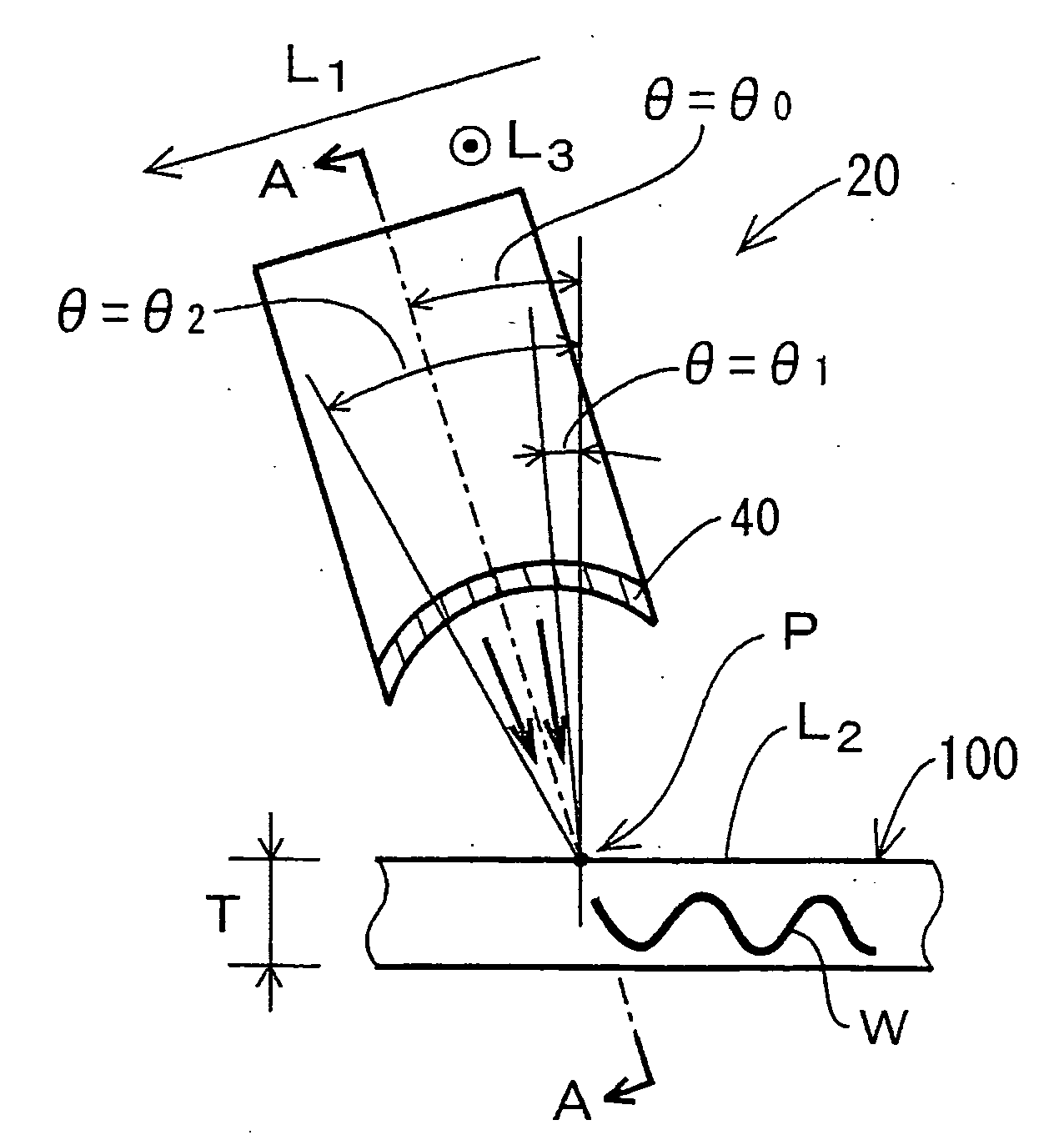
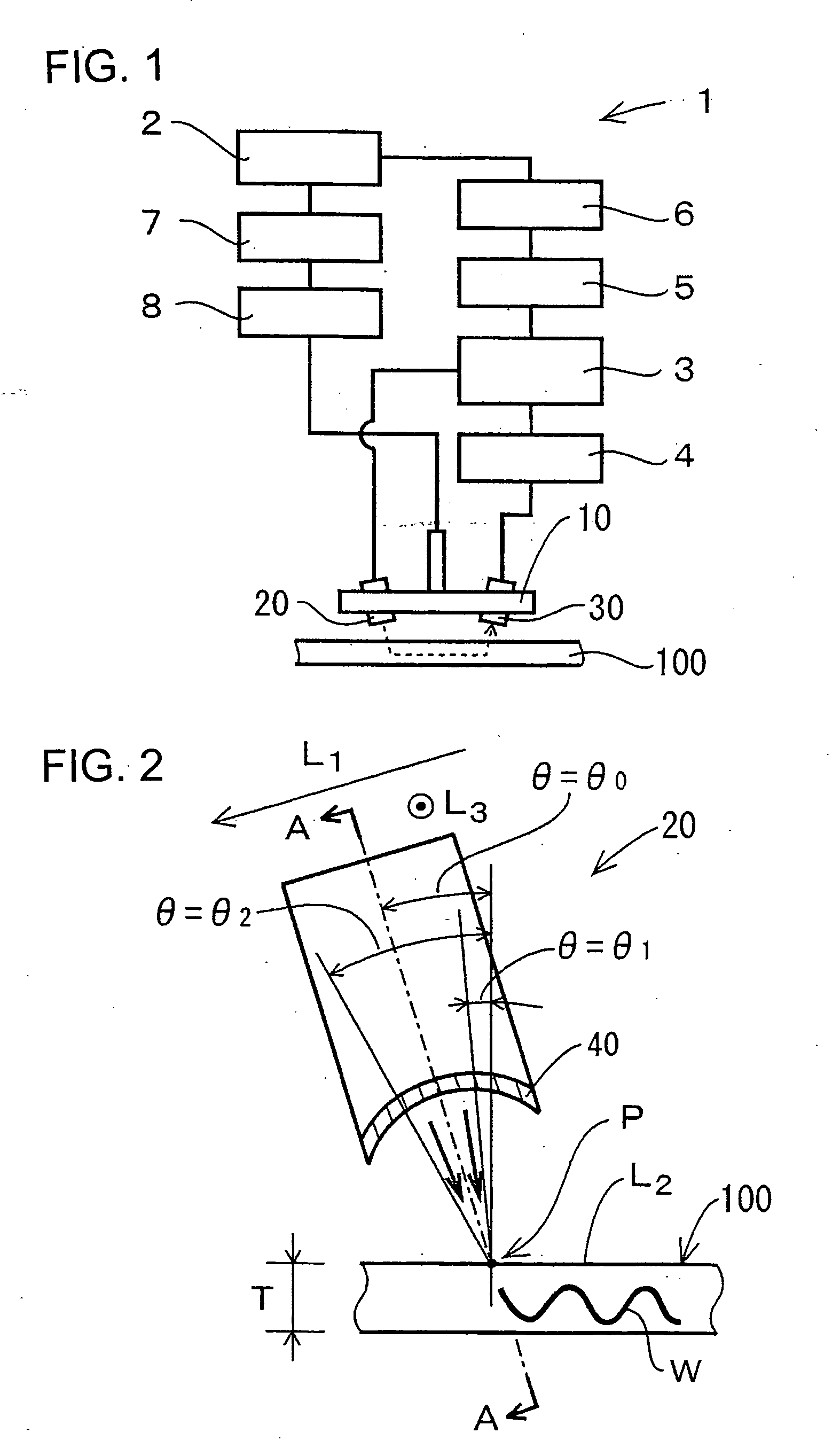
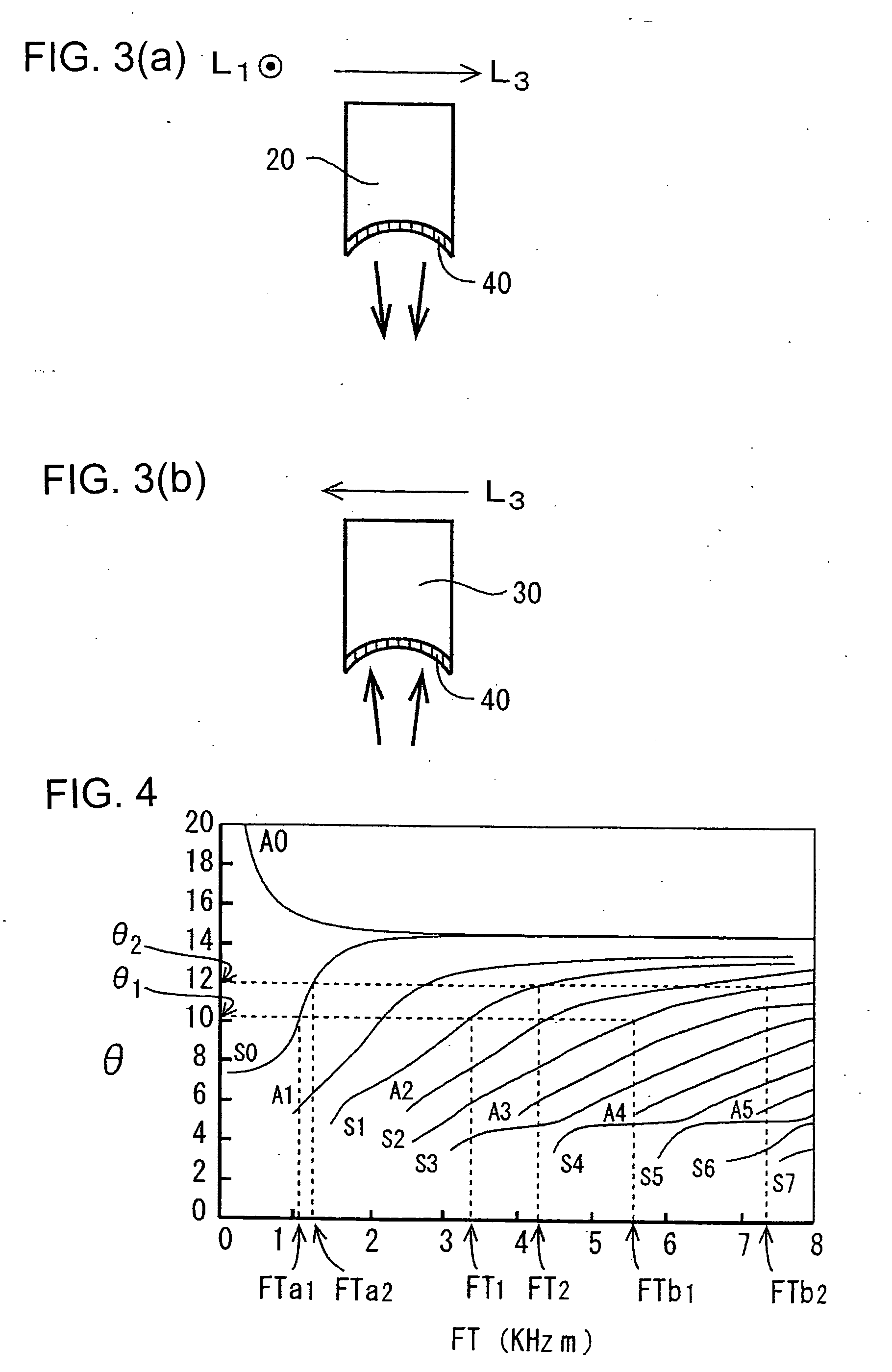
[0028]The present invention will be described in more detail, referring to the accompanied drawings. FIG. 1 illustrates an ultrasonic testing device 1 according to the present invention. The ultrasonic testing device 1 is arranged for transmitting an ultrasonic wave from a transmitter 20 in a scan head 10 with the use of a plate wave transducer 3 which is controlled by a personal computer 2 (referred to as a PC hereinafter) and receiving at a receiver 30 the returning of the ultrasonic wave which is then transferred via a pre-amplifier 4, a filter 5, and an A / D converter 6 to the PC 2 where it is subjected to arithmetic operations. The PC 2 is also provided for starting the action of a scanner 8 through a scanner driver 7 to inspect any flaw in a test piece 100 with a scan head 10.

[0029]It is noted that the test piece 100 in this embodiment is a carbon fiber reinforced plastic (CFRP) material. As shown in FIG. 7, the received signal consists mainly of a test piece propagated wave Wi...


PUM


Abstract

An ultrasonic wave propagating method capable of propagating plate waves between a probe and a test piece despite variations in the thickness or the surface angle of a test piece, and an ultrasonic propagating device and an ultrasonic testing device using this method. Ultrasonic waves are propagated between a probe (20) for transmitting or receiving ultrasonic waves and a test piece (100) for propagating plate waves. When propagating ultrasonic waves, a probe that can set an ultrasonic wave incident angle from the probe (20) to the test piece (100) and/or an ultrasonic wave receivable angle from the test piece to the probe in a plurality of states is used. A focal point type probe may be used as the above probe (20). When this type of a probe is used, it is oriented such that an oscillating direction axis L1 in the direction of which a reference axis along the propagation route of ultrasonic waves is oscillated around the focal point of the probe crosses the propagation element surface L2 including the test piece surface of a ultrasonic wave propagation element.

Description

FIELD OF THE INVENTION[0001]The present invention relates to an ultrasonic wave testing method for propagating an ultrasonic wave between a probe which transmits and receives the ultrasonic wave and a test piece through which its generation plate wave is propagated thus to examine the test piece and to an ultrasonic testing device using the method.BACKGROUND OF THE INVENTION[0002]Such a test method with an ultrasonic wave propagated through the air as shown in FIG. 8 is known where the ultrasonic wave is propagated from a probe to a test piece which in turn generates a plate wave and allows the probe to measure the plate wave generated in the test piece (See Patent Document 1).[0003]Another test method is also disclosed in Non-patent Document 1 for improving the intensity of transmission and reception of incident / leak signals with the use of a probe which is curved along the horizontal direction.[0004]Patent Document 1: Japanese Patent Laid-open Publication No. 2005-055197.[0005]Non...

Claims


Application Information

Patent Timeline
IPC IPC(8): G01N29/07
CPCG01N29/223G01N29/2456G01N29/2487G01N2291/0231G01N2291/2694G01N2291/0427G01N2291/056G01N2291/101G01N2291/2693G01N2291/0425
Inventor YABUSHITA, HIDEKINAGAI, TATSUYUKIMATSUBARA, SHIGEYUKINEMOTO, NORIOMIYAMOTO, HIROSHI
Owner JAPAN AEROSPACE EXPLORATION AGENCY
Why Eureka
Try Eureka