Sheathed-element glow plug

a glow plug and element technology, applied in the field of shielded element glow plugs, can solve the problems of impaired pressure measurement, damage to the diaphragm, and significant stress on the diaphragm, and achieve the effect of reliable measurement of the pressure prevailing in the chamber

Inactive Publication Date: 2009-07-02
ROBERT BOSCH GMBH +1
View PDF15 Cites 20 Cited by
  • Summary
  • Abstract
  • Description
  • Claims
  • Application Information

AI Technical Summary

Benefits of technology

[0004]The sheathed-element glow plug according to example embodiments of the present invention, having the features described herein, has the advantage that the pressure sensor is able to have a certain prestressing applied to it. Thereby, in particular, possible gaps between the individual elements in the force path between the heating pin and the pressure sensor are able to be prevented, so that a reliable measurement of the pressure prevailing in the chamber is made possible.

Problems solved by technology

The pressure-measuring glow plug described in German Published Patent Application No. 103 43 521 has the disadvantage that the diaphragm is exposed to considerable stresses when the pressure-measuring glow plug is incorporated in the cylinder, because of the required installation force, whereby damage to the diaphragm may occur.
Besides, the diaphragm is situated in the force path between the heating pin and the pressure sensor, so that the pressure measurement is impaired.
A further disadvantage of the pressure-measuring glow plug is the great distance of the pressure measuring sensor from the conical seal of the plug element, since, because of that, natural vibrations of the pressure-measuring glow plug are favored at low frequencies.
These natural frequencies may make the measurement of the pressure worse or impossible, and in an extreme case may result in the destruction of the pressure-measuring glow plug.
The components of the force path of the sheathed-element glow plug may have greatly different coefficients of thermal expansion, so that temperature changes lead to substantial differences in the expansion of the components.
In particular, instead of a ceramic force transmission sleeve, which is costly to process, a force transmission sleeve made of a metal may be used.

Method used


Image

  • Sheathed-element glow plug
  • Sheathed-element glow plug
  • Sheathed-element glow plug

Examples


Embodiment Construction

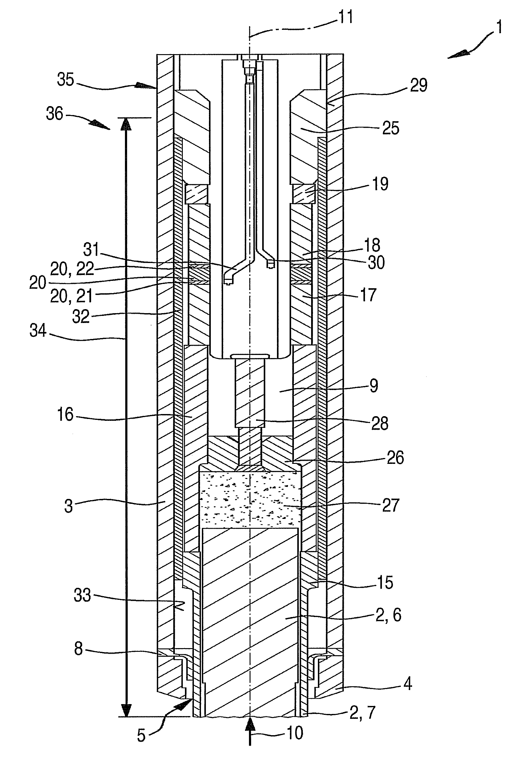
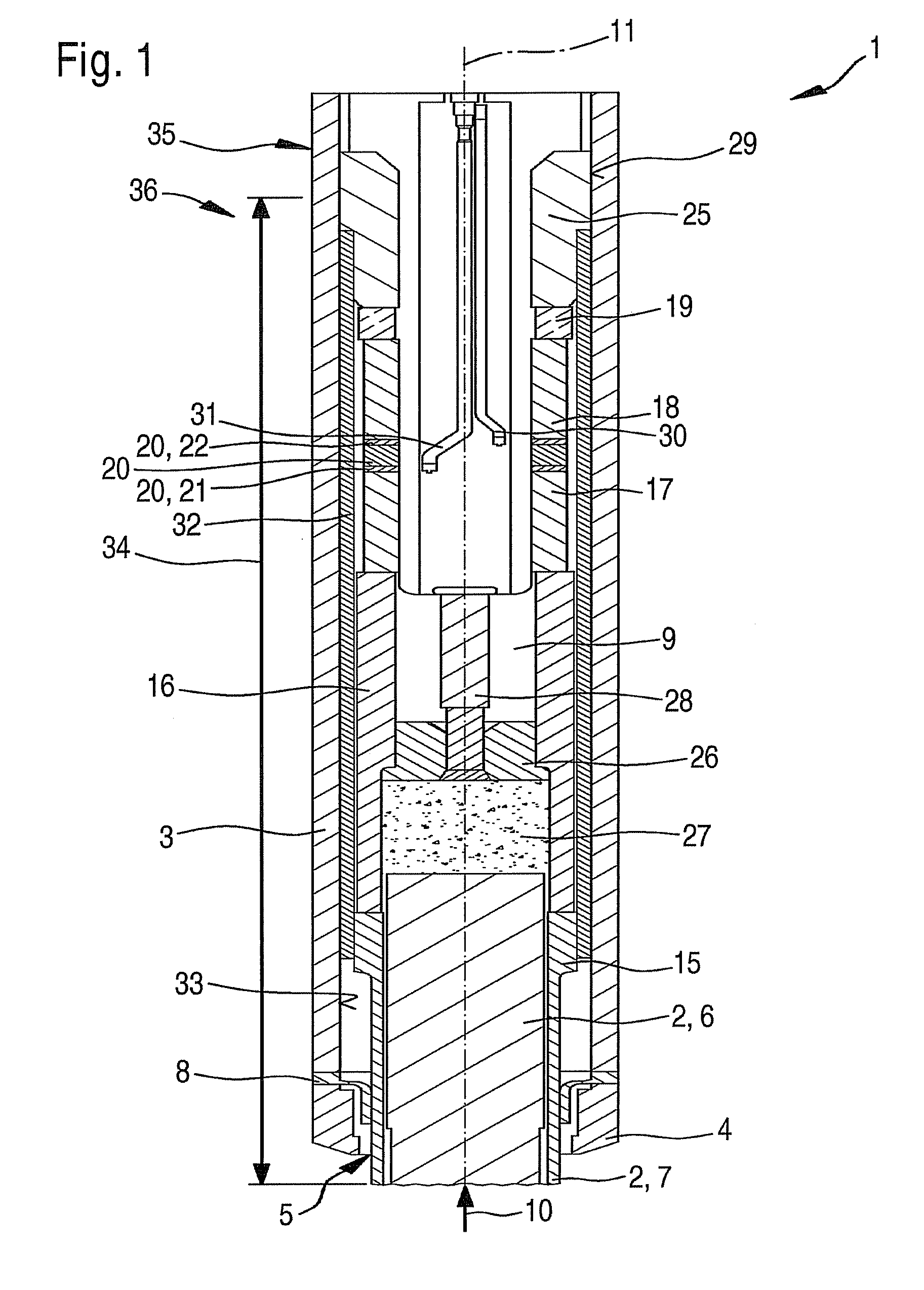
[0014]FIG. 1 shows a first exemplary embodiment of a sheathed-element glow plug 1 in an axial sectional representation. Sheathed-element glow plug 1 may be developed particularly as sheathed-element glow plug 1 for an air-compressing, self-igniting internal combustion engine. In the case of prechamber engines and swirl chamber engines, a pin-shaped heating element 2 of sheathed-element glow plug 1 extends into the chamber of the internal combustion engine and, in the case of engines having direct injections, into a chamber of the engine. However, sheathed-element glow plug 1 is also suitable for other applications.

[0015]Sheathed-element glow plug 1 has a housing 3. The housing includes a sealing cone 4, pin-shaped heating element 2 extending out of housing 3 into the chamber of the internal combustion engine, at an opening 5 of sealing cone 4 on the chamber side. Pin-shaped heating element 2 includes a ceramic heating member 6 and a support member 7 which circumferentially encloses ...


PUM


Abstract

A sheathed-element glow plug is used to be situated in a chamber in an internal combustion engine. The sheathed-element glow plug has a housing, a pin-shaped heating element, which extends partially from the housing and a pressure sensor which is situated in an inner chamber of the housing. A prestressing sleeve is provided, in this context, which applies a prestressing to the pressure sensor.

Description

FIELD OF THE INVENTION[0001]The present invention relates to a sheathed-element glow plug to be situated in a chamber in an internal combustion engine. The present invention also relates to a sheathed-element glow plug to be situated in a prechamber, swirl chamber or combustion chamber of an air compressing, self-igniting internal combustion engine.BACKGROUND INFORMATION[0002]A pressure-measuring glow plug for a Diesel engine is described in German Published Patent Application No. 103 43 521. The pressure-measuring glow plug has a plug element and a heating pin situated in the plug element. Furthermore, between the heating pin and the plug element there is a pressure sensor, the pressure sensor being influenced by the pressure, in the combustion chamber of the cylinder, that is transmitted by the heating pin. A diaphragm is also provided which seals the pressure sensor from the combustion chamber.[0003]The pressure-measuring glow plug described in German Published Patent Application...

Claims


Application Information

Patent Timeline
Patent Type & Authority Applications(United States)
IPC IPC(8): F23Q7/22
CPCF02P19/028F23Q7/001F23Q2007/002G01L23/222G01L23/10
Inventor KERN, CHRISTOPHHESS, REINHOLDZACH, REIKOKLEINDL, MICHAELWOLFER, PETERSCHOTT, STEFFENCAVALLONI, CLAUDIOSALTIKOV, PAVLOMUELLER, MICHAELBERTOLA, ANDREA
Owner ROBERT BOSCH GMBH
Why Eureka
Try Eureka