Wig

Inactive Publication Date: 2009-07-02
ADERANS HLDG CO LTD
View PDF5 Cites 13 Cited by
  • Summary
  • Abstract
  • Description
  • Claims
  • Application Information

AI Technical Summary

Benefits of technology

[0019]According to the present invention in Claims 1 through 6, the direction of the curl of the hair pieces is determined depending upon the direction in which the hair materials are fastened to the wig base, and a predetermined hair design results. For example, when the hair materials are fixed to the wig base in a state in which they are aligned in the same direction, the curl of the hair pieces of these hair materials is aligned in the same direction. When a large number of hair materials are fastened to the wig base in fixed amounts in different directions, the curls of the hair pieces of these hair materials are oriented in different directions. Thus, through appropriate selection of hair material fixing directions with respect to the wig base, it is possible to obtain wigs for a variety of hair designs. Further, it is possible to maintain the curl imparted to the hair pieces of the hair materials in a satisfactory state for a long period of time. In the construction of the present invention, the hair materials are fixed to the wig base with their directions determined, so the direction of the curl of the hair pieces is determined. Thus, after fixing the hair materials to the wig base, it is possible to easily obtain a wig in whi

Problems solved by technology

Particularly, in case the user is a lady, an elegant and unique fashionableness in hair styles as well as increase of hair in volume is quite often required, and it is difficult to meet such requirements of various hair styles with straight hairs, which only provide a rather low flexibility.
However, according to the above-described configuration, in which curl is imparted to all the hair materials fastened to the wig base through post-processing, the folded portion 1a of each hair material 1 is already fixed to a wig base 2 as shown in FIG. 21, so it is impossible to secure a sufficient length for the remaining hair piece 1b to impart curl thereto.
As a result, the hair piece 1b can not be sufficiently wound around a curl imparting means 3 such as a rod or a curler, and it

Method used


Image

  • Wig
  • Wig
  • Wig

Examples


first embodiment

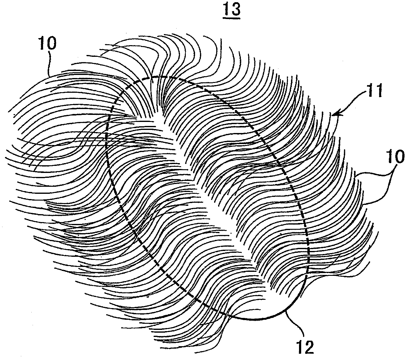
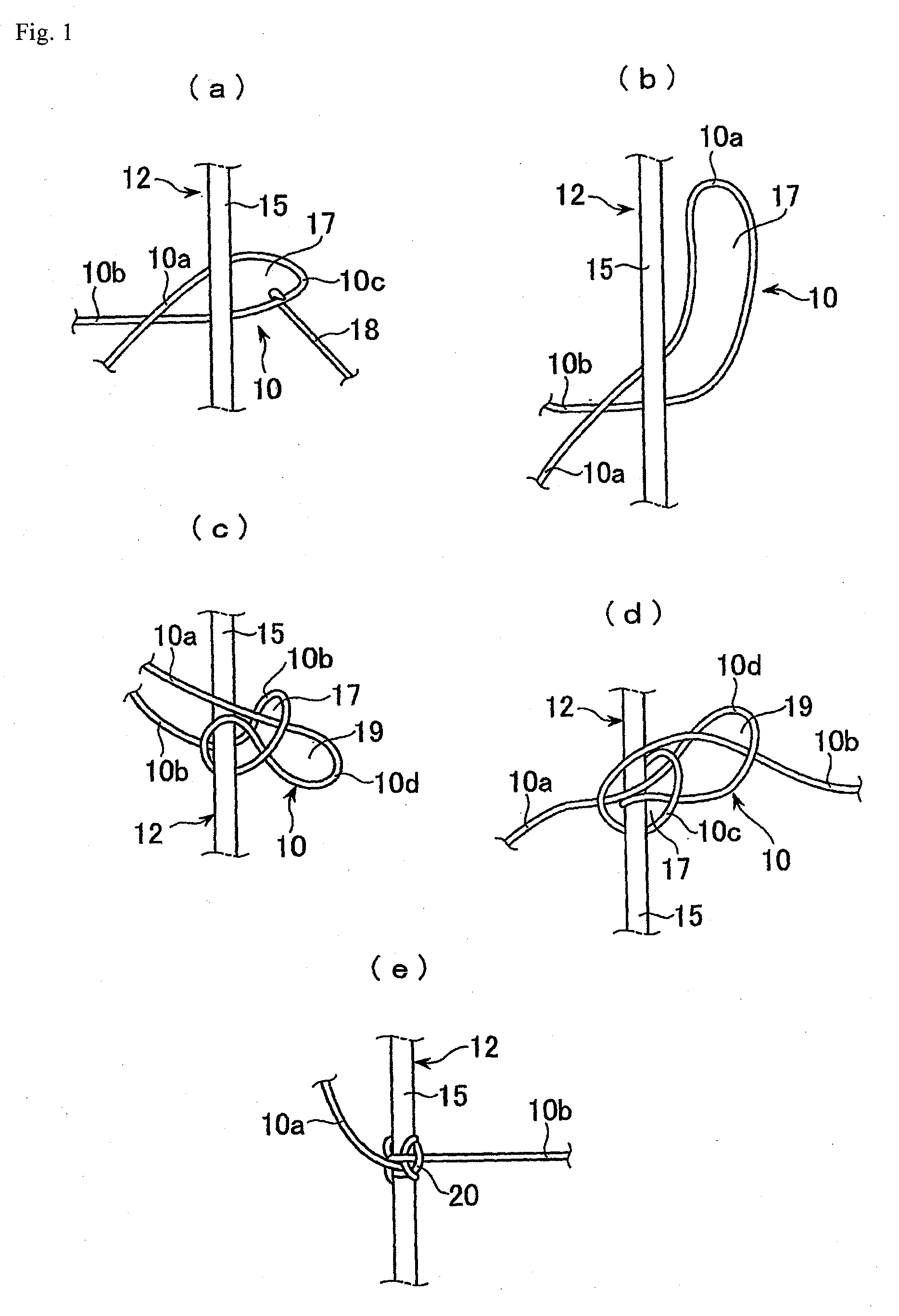
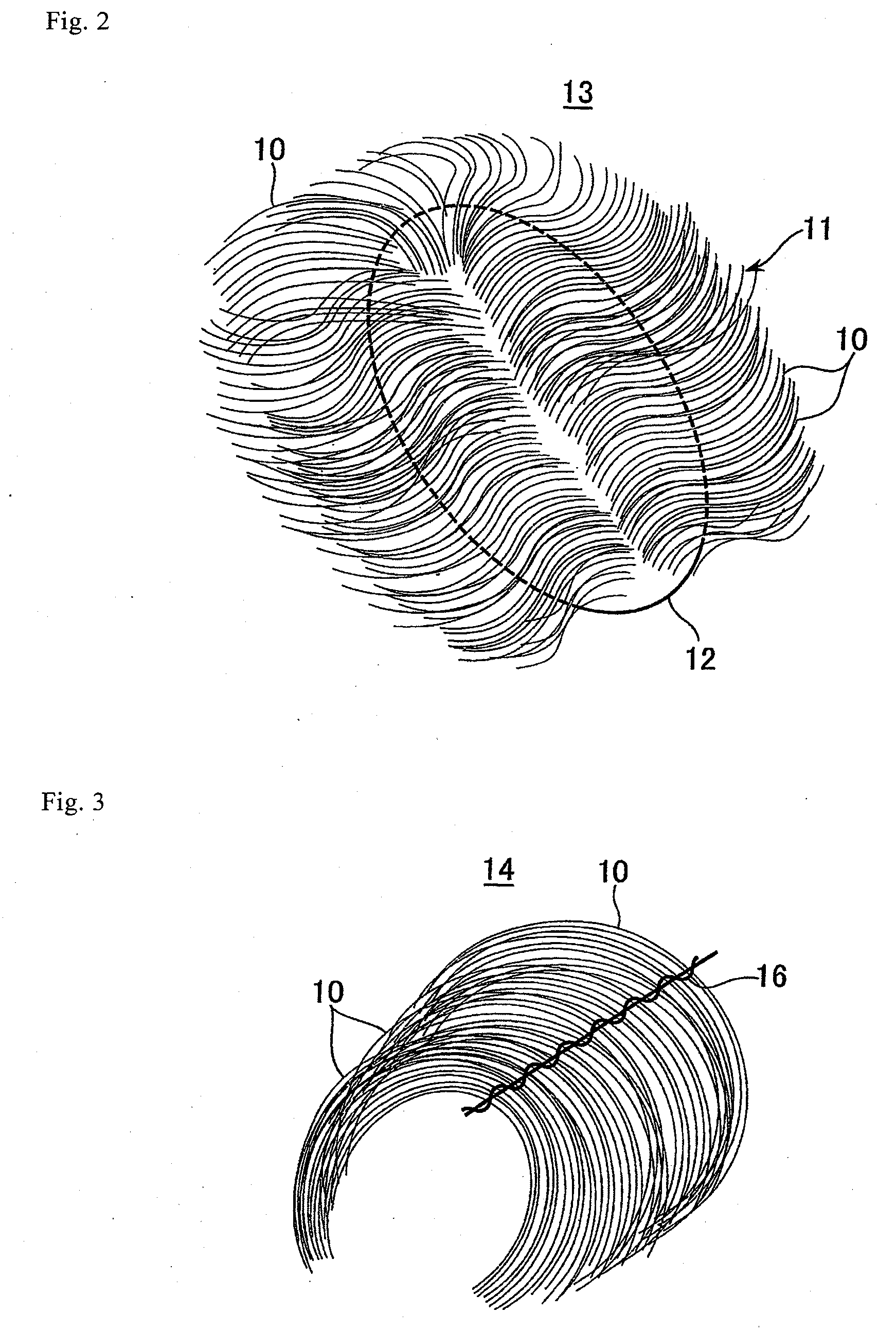
[0043]In the following, embodiments of the present invention will be described with reference to FIGS. 1 through 20. Of the drawings, FIGS. 1 through 5 show the present invention. FIGS. 1(a) through 1(e) are plan views illustrating the operation of fastening a hair material to a filament of a wig base in the form of a net, FIG. 2 is a perspective view of a wig, FIG. 3 is a perspective view of a weft, FIGS. 4(a) through 4(d) are perspective views of a single hair material, and FIG. 5 is a front view of hair materials as fastened to a filament of a wig base.

[0044]In the first embodiment of the present invention shown in FIGS. 1 through 5, a large number of hair materials 10 are fastened to a wig base 12 as hair 11 to form a wig 13 as shown in FIG. 2. As the hair materials 10, human hairs or synthetic resin hairs are used. In the state of a weft 14 prior to the fastening to the wig base 12, curl is imparted to hair pieces 10a, 10b beforehand. When large number of hair materials 10 are ...

third embodiment

[0062]Of the drawings, FIGS. 7 through 16 show the FIG. 7 is a perspective view illustrating the operation of blending hair materials, FIG. 8 is a plan view of a sewn weft, FIG. 9 is a plan view of a weft as placed on a sheet material, FIG. 10 is a plan view of a weft placed on a sheet material as combed, FIG. 11 is a sectional view of a weft on a sheet material, FIG. 12 is a plan view illustrating how hair a tuft and a sheet material are wound around a pipe member, FIG. 13 is a sectional view showing a weft and a sheet material as wound around a pipe member, FIG. 14 is a perspective view showing, like FIG. 13, hair a tuft and a sheet material as wound around a pipe member, FIG. 15 is a front view of a hair material as fastened to a filament, and FIG. 16 is a plan view of hair materials drawn out of hair a tuft.

[0063]The third embodiment shown in FIGS. 7 through 16 is suitable for imparting curl to human hairs as the hair materials 10 (including human hairs from which the cuticles ...

fifth embodiment

[0088]In this way, in the fifth embodiment, it is possible to apply moist air and dry air continuously with ease, without using any special device, through a combination of the material and weight per unit area [metuske] of the non-woven fabric wound together with the weft 14, the aluminum pipe member 33, and the aluminum foil 37, and through adjustment of the temperature and time of the heat treatment, thereby making it possible to obtain a curl of still higher retaining property.

[0089]Next, the sixth embodiment of the present invention will be described with reference FIGS. 7 through 16 common to the third through fifth embodiments plus FIGS. 19 and 20. A detailed description of the components that are the same as those of the third through fifth embodiments will be omitted. This embodiment is suitable for an artificial hair described below. That is, an artificial hair of a core / sheath structure is preferable, with the core portion being formed of a semi-aromatic polyamide with a ...


PUM

PropertyMeasurementUnit
Timeaaaaaaaaaa
Timeaaaaaaaaaa
Surface smoothnessaaaaaaaaaa

Abstract

A hair material for a wig is preliminarily curled and then bound to a wig base to thereby orient the curled hair in a definite direction. A folded part (10c) of a hair material (10) is penetrated from one side of a filament (15) to the other side under a wig base (12) so that a first loop (17) is formed in the inner side of the folded part (10c). A curved part (10d) is inserted though the first loop (17) so that a second loop (19) is formed in the inner side of the curved part (10d). A part (10b) of the hair material is inserted through the second loop (19). Next, the hair material parts (10a, 10b) are pulled in directions opposite to each other and tied with the filament (15) to (20). Thus, the hair material (10) is bound to the filament (15).

Description

TECHNICAL FIELD[0001]The present invention relates to a wig to be worn to a head in full or in part, and more specifically, to a wig comprising a wig base and curled hair materials fixed to the wig base.BACKGROUND ART[0002]Conventionally, hair materials used for wigs have generally been straight hairs. In recent years, however, there are a variety of hair styles. Particularly, in case the user is a lady, an elegant and unique fashionableness in hair styles as well as increase of hair in volume is quite often required, and it is difficult to meet such requirements of various hair styles with straight hairs, which only provide a rather low flexibility.[0003]To solve this problem, there is known, for example, a technique as disclosed in Japan Patent Application Laid-open 64-40606 A. According to the technique disclosed in this specification, a hair material is folded into two, the folded portion is fastened to the front portion of a wig base, the hair material is curled or turned over ...

Claims


Application Information

Patent Timeline
IPC IPC(8): A41G3/00
CPCA41G3/0066A41G3/00D01F6/60A41G3/0083D01F6/40
Inventor SOTOKAWA, YASUHISASUGAI, KATSUOSHIRAKASHI, YUTAKASATO, TOSHIHIKOIRIKURA, AKEMI
Owner ADERANS HLDG CO LTD
Why Eureka
Try Eureka