Check patentability & draft patents in minutes with Patsnap Eureka AI!

Double-wall-tube heat exchanger

Inactive Publication Date: 2009-07-02
KEIHIN THERMAL TECH CORP
View PDF13 Cites 27 Cited by
  • Summary
  • Abstract
  • Description
  • Claims
  • Application Information

AI Technical Summary

Benefits of technology

[0006]An object of the present invention is to solve the above-mentioned problem and to provide a double-wall-tube heat exchanger exhibiting excellent heat exchange performance.

Problems solved by technology

However, the intermediate heat exchanger described in the above-mentioned publication involves the following problem: the area of heat transfer between the high-temperature refrigerant flow path and the low-temperature refrigerant flow path is small, resulting in insufficient heat exchange performance.

Method used


Image

  • Double-wall-tube heat exchanger
  • Double-wall-tube heat exchanger
  • Double-wall-tube heat exchanger

Examples


embodiment 1

[0056]The present embodiment is shown in FIGS. 1 to 7.

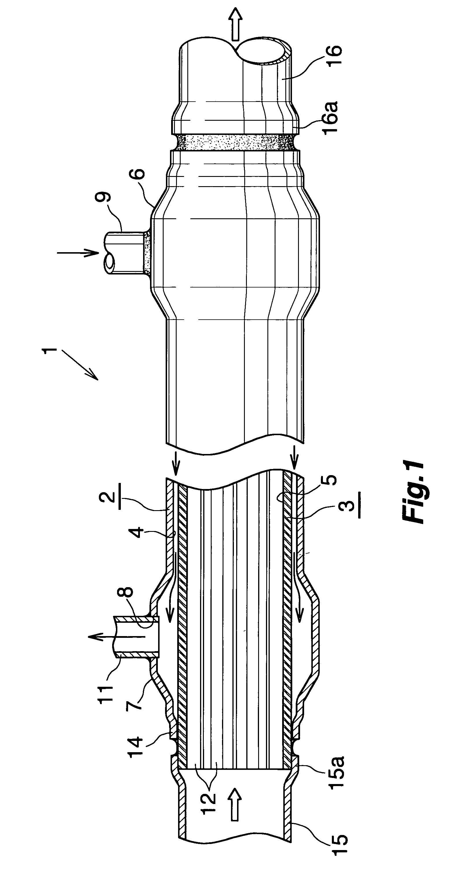
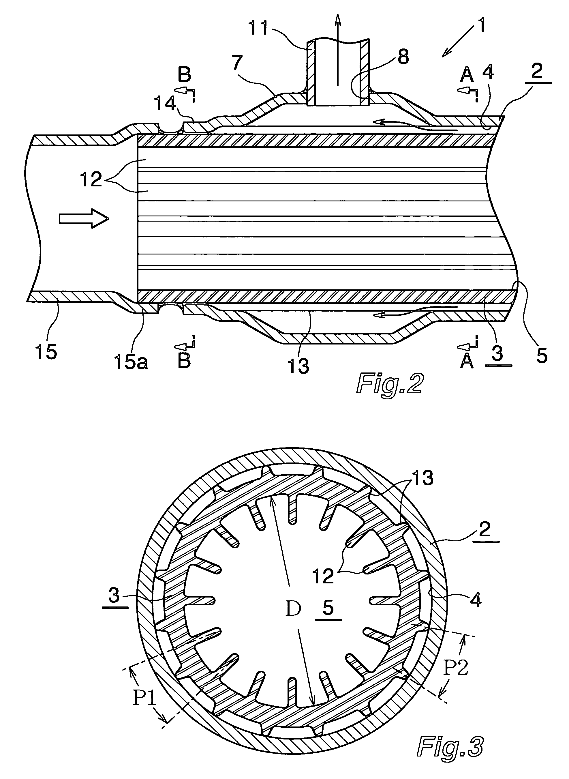
[0057]FIG. 1 shows the configuration of a double-wall-tube heat exchanger according to Embodiment 1 of the present invention. FIGS. 2 to 6 show the configurations of essential portions of the double-wall-tube heat exchanger. FIG. 7 shows a refrigeration system which uses the double-wall-tube heat exchanger of Embodiment 1 as an intermediate heat exchanger.

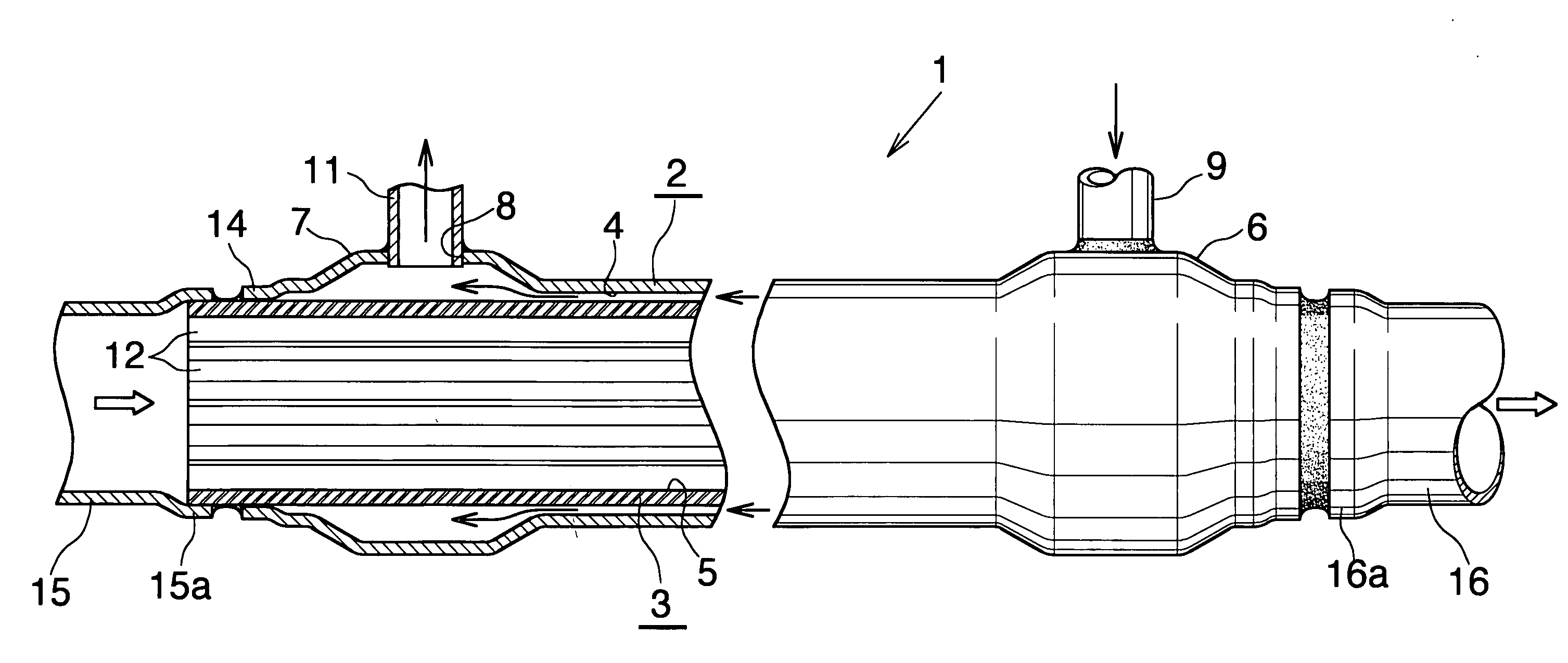
[0058]In FIGS. 1 to 5, a double-wall-tube heat exchanger 1 includes an outer tube 2 and an inner tube 3. The outer tube 2 is formed of an aluminum extrudate having a circular cross section. The inner tube 3 is formed of an aluminum extrudate having a circular cross section and is inserted concentrically into and spaced apart from the outer tube 2. A clearance between the outer tube 2 and the inner tube 3 serves as a first refrigerant flow path 4. The interior of the inner tube 3 serves as a second refrigerant flow path 5.

[0059]The outer tube 2 has expanded tube portions 6 and 7 ...

embodiment 2

[0072]The present embodiment is shown in FIGS. 13 to 17.

[0073]FIGS. 13 to 17 show the configurations of essential portions of a double-wall-tube heat exchanger according to Embodiment 2 of the present invention.

[0074]In the case of the double-wall-tube heat exchanger 31 of Embodiment 2, the outer tube 2 has a plurality of elongated projections 32 formed integrally with the inner circumferential surface of the outer tube 2. The elongated projections 32 project radially inward, extend in the longitudinal direction, and are arranged at equal circumferential intervals. Also, the outer tube 2 does not have expanded tube portions at opposite end portions thereof.

[0075]The inner tube 3 has diameter-reduced tube portions 33 located slightly longitudinally inward of the opposite ends thereof. A refrigerant inlet (not shown) is formed in the wall of the outer tube 2 at a position corresponding to one diameter-reduced tube portion (not shown). The refrigerant outlet 8 is formed in the wall of ...


PUM


Abstract

A double-wall-tube heat exchanger has an outer tube, and an inner tube disposed concentrically in and spaced apart from the outer tube. A clearance between the outer tube and the inner tube and the interior of the inner tube serve as respective refrigerant flow paths. The inner tube has a plurality of interior fins formed on its inner circumferential surface. The interior fins project radially inward; extend in a longitudinal direction of the inner tube; and are arranged at circumferential intervals. The inner tube has a plurality of elongated projections formed on its outer circumferential surface. The elongated projections project radially outward; extend in the longitudinal direction; and are arranged at circumferential intervals. The interior fins are greater in height than the elongated projections. The double-wall-tube heat exchanger exhibits excellent heat exchange performance.

Description

BACKGROUND OF THE INVENTION[0001]The present invention relates to a double-wall-tube heat exchanger and, more particularly, to a double-wall-tube heat exchanger which has an outer tube, and an inner tube provided in and spaced apart from the outer tube.[0002]Herein, the term “condenser” refers to not only an ordinary condenser but also a subcooling condenser, which has a condensing section and a subcooling section.[0003]A conventionally proposed refrigeration system for use in a car air conditioner includes a compressor; a condenser having a condensing section and a subcooling section; an evaporator; an expansion valve serving as a pressure-reducing device; a vapor-liquid separator; and an intermediate heat exchanger disposed between the condenser and the evaporator and adapted to perform heat exchange between a high-temperature refrigerant from the subcooling section of the condenser and a low-temperature refrigerant from the evaporator (as disclosed in, for example, Japanese Paten...

Claims


Application Information

Patent Timeline
IPC IPC(8): F28F1/20
CPCF25B40/00F28D7/106F28F1/006F28F1/422F28F1/36F28F1/40F28F1/42F28F1/16
Inventor TOKIZAKI, KAZUMIHIGASHIYAMA, NAOHISAARINO, KOUTATAKAHASHI, YASUHIRO
Owner KEIHIN THERMAL TECH CORP
Features
  • R&D
  • Intellectual Property
  • Life Sciences
  • Materials
  • Tech Scout
  • Unparalleled Data Quality
  • Higher Quality Content
  • 60% Fewer Hallucinations
Learn More