Wastewater treatment plant

a technology for wastewater treatment and wastewater, applied in the direction of vehicle wash waste water treatment, water treatment parameter control, sedimentation settling tanks, etc., can solve the problems of increasing the problem of particulate waste and sludge disposal, time-consuming and costly maintenance of these conventional oil separators,

Inactive Publication Date: 2009-07-02
AQUENOX
View PDF11 Cites 14 Cited by
  • Summary
  • Abstract
  • Description
  • Claims
  • Application Information

AI Technical Summary

Benefits of technology

[0006]It is therefore an object of the invention to provide a process for treatment of wastewater which reduces the problem of the prior art discussed above.

Problems solved by technology

However maintenance of these conventional oil separators is time consuming and costly and in some cases is inefficient.
An additional problem with conventional wastewater treatment plants such as those described above have included the problem of addition of polymeric flocculants such as polyelectrolytes to post treatment apparatus after electrolysis or electrocoagulation which increases the problems of disposal of particulate waste and sludge.

Method used


Image

  • Wastewater treatment plant
  • Wastewater treatment plant
  • Wastewater treatment plant

Examples


Embodiment Construction

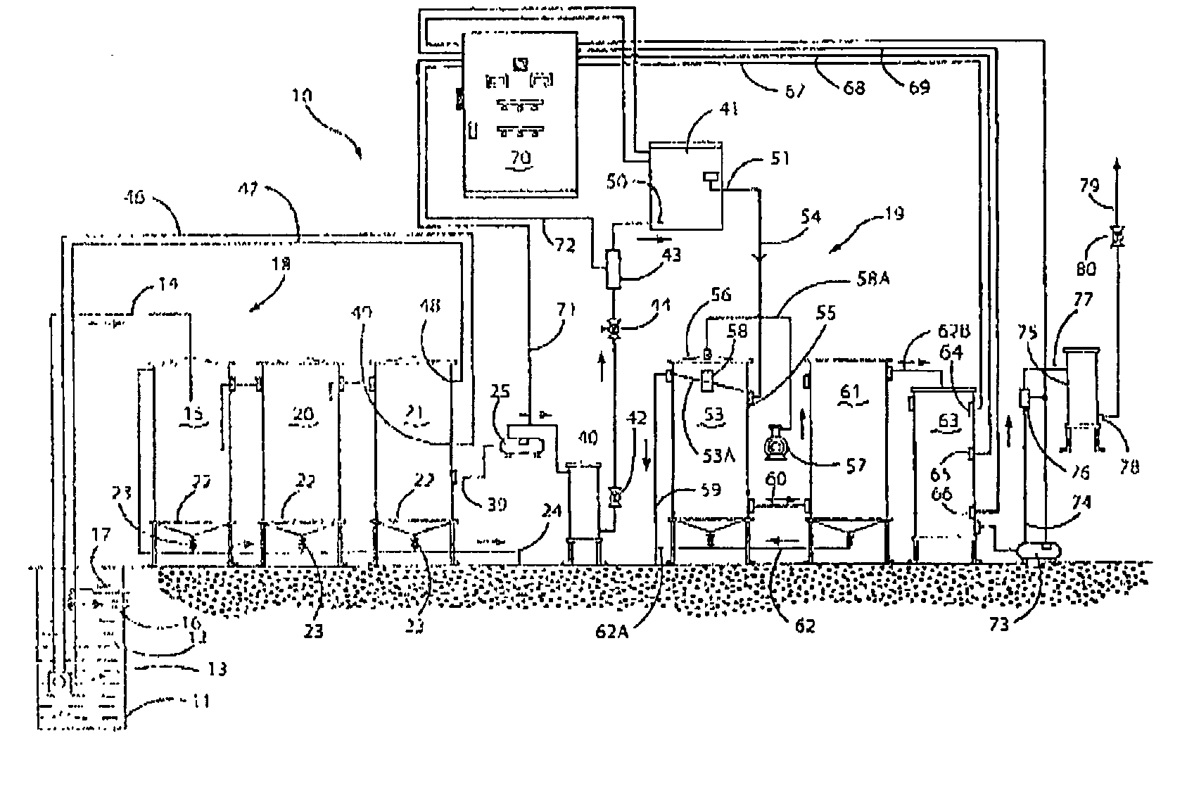
[0020]In the treatment plant shown in FIG. 1 there is provided a complete wastewater treatment plant 10 having a sump or underground holding pit 11 for wastewater effluent 12 which has a submersible pump 13, conduit 14 for passage of effluent to settling tank 15, overflow port 16 and return port 17 for recycled purified waste which is returned to sump 11 from a carwash (not shown) where the purified wastewater after being applied in washing a vehicle (not shown) is returned through a return conduit (not shown) which communicates with return port 17.

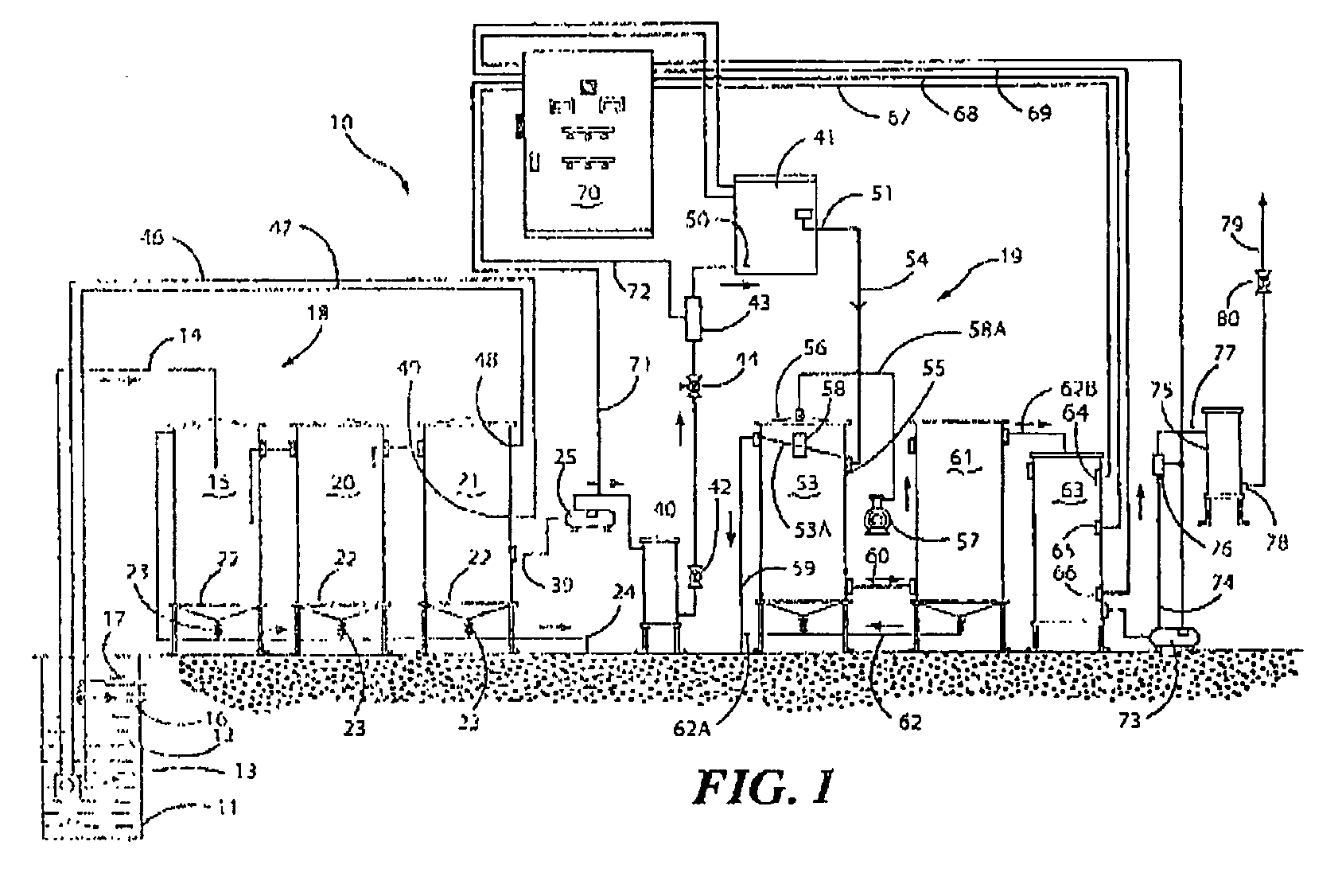
[0021]FIG. 2 shows a detailed view of the pre-treatment assembly 18 shown in FIG. 1 which comprises settling tank 15, settling tank 20 and settling tank 21 all connected in series for the flow of wastewater. Settling tank 15 has a conical drainage base 22 which is provided with a ball valve 23 which is a ball valve. Sediment waste is discharged from the base 22 through valve 23 into sediment waste conduit 24. This process is continued in ...


PUM

PropertyMeasurementUnit
conductivityaaaaaaaaaa
gravity separationaaaaaaaaaa
shapeaaaaaaaaaa

Abstract

Apparatus for treatment of wastewater which has pre-treatment apparatus for treatment of wastewater which has at least two separation tanks connected in series through which the wastewater is passed wherein there is provided a vertically oriented baffle pipe having a closed top and an open bottom which is attached to or located adjacent a side wall of a first tank Which traps triglycerides, fats or other particulate impurities in the wastewater for subsequent passage into a second tank through a primary conduit which interconnects the first and second tanks. The apparatus also includes post-treatment apparatus for treatment of wastewater after passing through an electrocoagulation cell incorporating at least one coagulation tank having a baffle located below a top end of the coagulation tank which has a spray nozzle associated therewith for washing floc off an interior of the tank whereby the floc is discharged through a conduit which extends through a side wall of the tank below the baffle.

Description

FIELD OF THE INVENTION[0001]This invention relates to a treatment plant for wastewater which utilises an electrocoagulation cell.BACKGROUND OF THE INVENTION[0002]Hitherto conventional electrocoagulation treatment plants as described for example in WO 20041046045 and WO 03 / 086982 have utilised a pre-treatment assembly which may comprise one or more filters to remove solid contaminants from the wastewater, a mixing tank for the addition electrolytes to increase the conductivity of the wastewater and the use of flocculants or thickening agents to assist in efficient disposal of sludge. There also may be included an electrocoagulation cell and post treatment assembly which comprises one or more coagulation tanks to remove solid particles contained in the wastewater. Flocculants may also be added to accelerate gravity separation of such solid particles.[0003]Reference also may be made to Japanese Patent Application 2004066037 which refers to a waste treatment plant especially for car was...

Claims


Application Information

Patent Timeline
Patent Type & Authority Applications(United States)
IPC IPC(8): C02F1/52
CPCB01D17/0211B01D21/02C02F1/001C02F1/40C02F2209/42C02F9/00C02F2101/32C02F2103/44C02F2209/40C02F1/463
Inventor TIGANI, JOSEPHUSHER, TERENCE G.
Owner AQUENOX
Why Eureka
Try Eureka