
Photovoltaic inverter interface device, system, and method

a photovoltaic inverter and interface device technology, applied in the field of solar energy conversion apparatus and methods, can solve the problems of reducing the load of the array, reducing the efficiency of the inverter, so as to increase the load of the photovoltaic array and reduce the voltage applied

Active Publication Date: 2009-07-02
SMA SOLAR TECH AG
View PDF51 Cites 60 Cited by
  • Summary
  • Abstract
  • Description
  • Claims
  • Application Information

AI Technical Summary

Benefits of technology

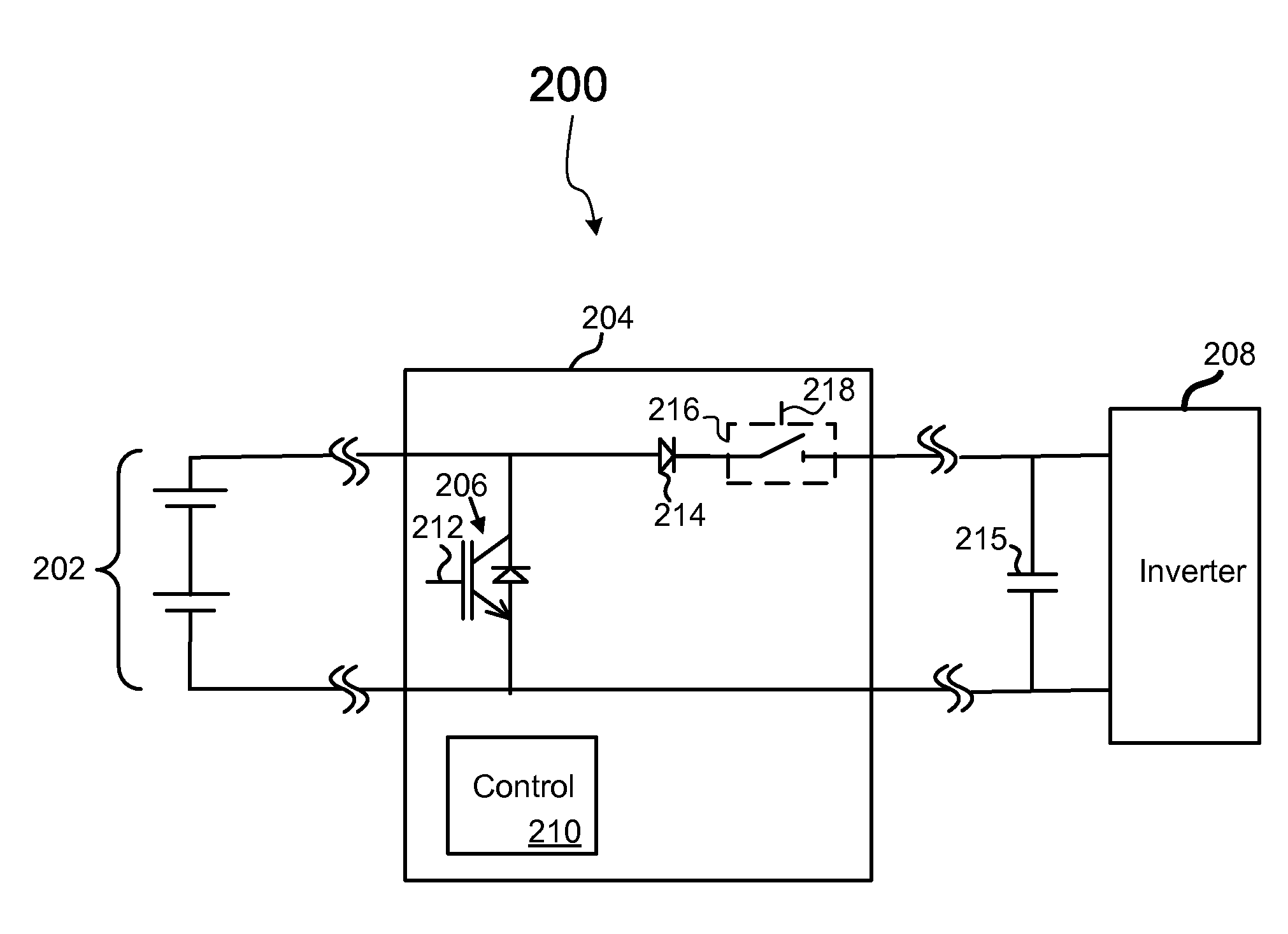
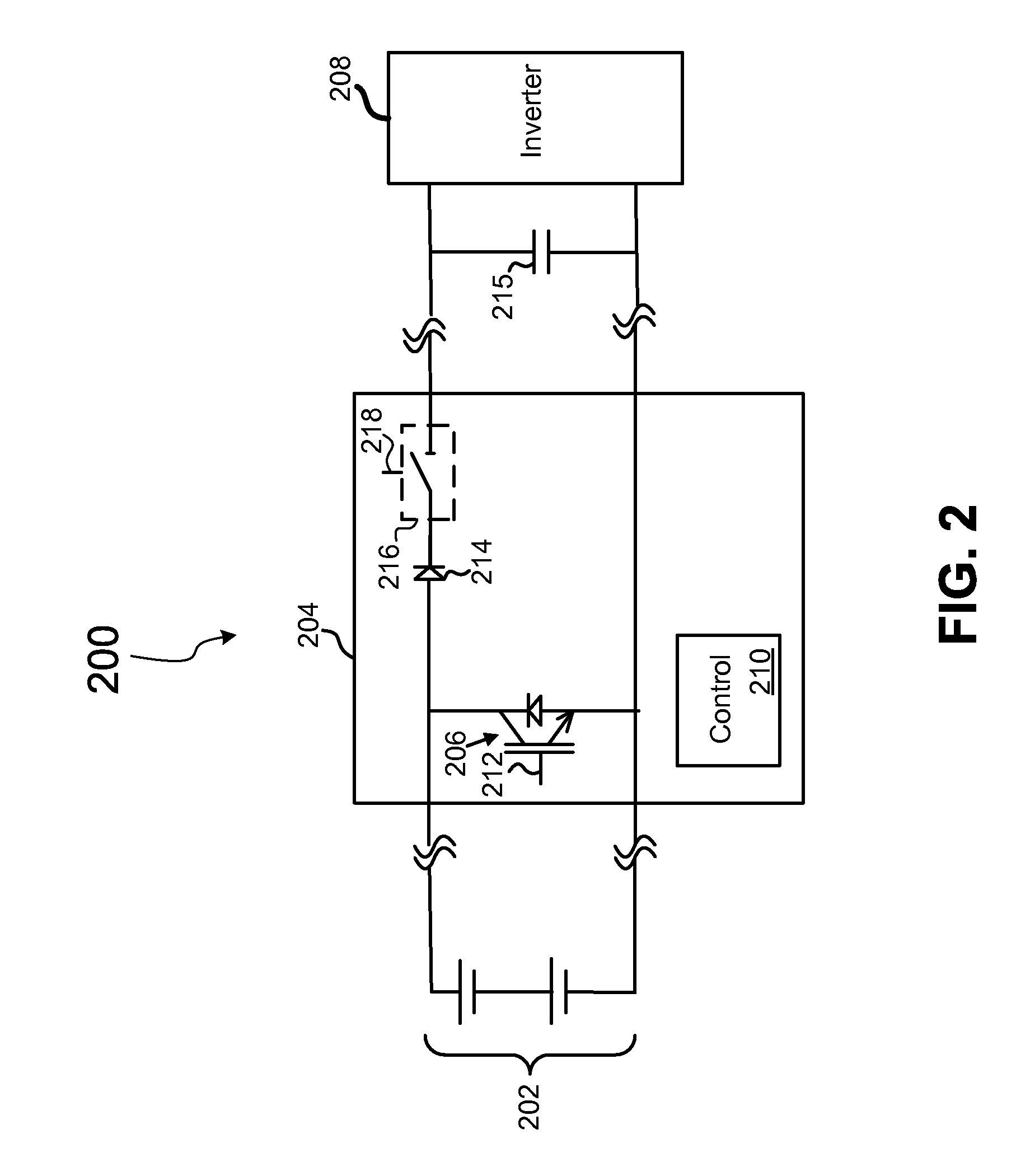
[0008]In one embodiment, the invention may be characterized as a photovoltaic system including a first and second inputs adapted to couple to a first and second rails of a photovoltaic array. In this embodiment, an inverter is configured to convert DC power from the photovoltaic array to AC power, and an interface portion, which is coupled to the first and second inputs and the inverter, is configured to isolate at least one of the first and second inputs from the inverter and to modulate an application of a voltage from the photovoltaic array to the inverter so as to increase a load on the photovoltaic array and to reduce the voltage applied from the photovoltaic array to the inverter.
[0010]In yet another embodiment, the invention may be characterized as a photovoltaic interface including two inputs capable of coupling to a photovoltaic array, the inputs configured to receive an initial voltage applied by the photovoltaic array. In addition, the interface in this embodiment includes two outputs capable of coupling to an inverter, the outputs configured to apply an operating voltage to the inverter. And a switching segment in this embodiment is configured to gradually place a load across the two inputs so as to reduce the initial voltage applied by the photovoltaic array to the operating voltage of the inverter.

Problems solved by technology

Although arrays are capable of applying high open loaded voltages, arrays rarely do so because once power is drawn from the arrays, the loaded voltage of the array drops substantially.
But inverters that are rated for higher voltages typically cost more and operate less efficiently than inverters that are designed to operate at lower voltages.
And as a consequence, inverters are often designed with silicon that is less efficient and costlier than silicon that could be used if the inverter did not have to be designed to handle high, open load voltages.
For example, inverters incorporating silicon rated for voltages around 1400 Volts incur substantially more losses, and cost substantially more than inverters that utilize silicon that is rated for 1200 Volt applications.

Method used


Image

  • Photovoltaic inverter interface device, system, and method
  • Photovoltaic inverter interface device, system, and method
  • Photovoltaic inverter interface device, system, and method

Examples


Embodiment Construction

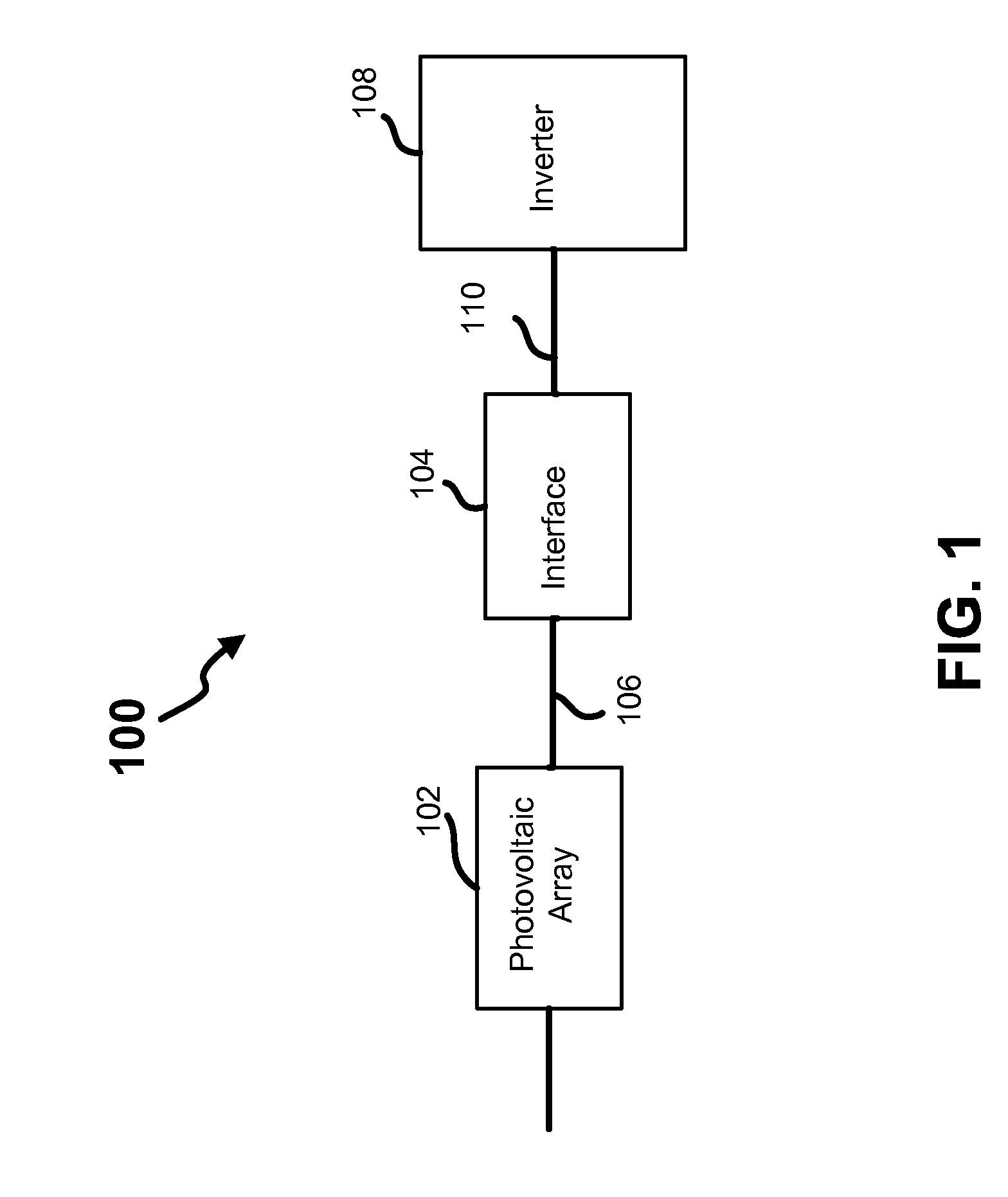
[0021]Referring now to the drawings, where like or similar elements are designated with identical reference numerals throughout the several views, and referring in particular to FIG. 1, it is a block diagram depicting a photovoltaic system 100, that includes a photovoltaic array 102 coupled to an inverter 108 via a photovoltaic (PV) interface 104.

[0022]In general, the photovoltaic array 102 converts solar energy to DC electrical power, which is converted to AC power (e.g., three-phase power) by the inverter 108. And the PV interface 204 generally operates to enable the inverter 108, which is designed to operate at lower voltages, to be utilized in connection with the PV array 102 that operates at least a portion of the time (e.g., while unloaded) at a voltage that exceeds the designed operating voltage of the inverter 108.

[0023]In many embodiments, the PV interface 104 is a low duty factor device, which operates only briefly during startup and / or shut down, to gradually connect or d...


PUM


Abstract

A photovoltaic system, method and apparatus are disclosed. In an exemplary embodiment, the system includes a first and second inputs adapted to couple to a first and second rails of a photovoltaic array; an inverter configured to convert DC power from the photovoltaic array to AC power; and an interface portion coupled to the first and second inputs and the inverter, the interface portion configured to isolate at least one of the first and second inputs from the inverter and to modulate an application of a voltage from the photovoltaic array to the inverter so as to increase a load on the photovoltaic array and to reduce the voltage applied from the photovoltaic array to the inverter.

Description

FIELD OF THE INVENTION[0001]This invention relates generally to apparatus and methods for converting solar energy to electrical energy, and more specifically to apparatus and methods for more efficient conversion of solar energy to electrical energy.BACKGROUND OF THE INVENTION[0002]The transformation of light energy into electrical energy using photovoltaic (PV) systems has been known for a long time and these photovoltaic systems are increasingly being implemented in residential, commercial, and industrial applications. Although developments and improvements have been made to these photovoltaic systems over the last few years to improve their efficiency, the efficiency of the photovoltaic systems is still a focal point for continuing to improve the economic viability of photovoltaic systems.[0003]Photovoltaic systems typically include, among other components, a photovoltaic array that generates DC power and an inverter that converts the DC power to AC power (e.g., single or three p...

Claims


Application Information

Patent Timeline
IPC IPC(8): H01H19/00
CPCY02E10/563Y10S136/291H02J3/383H02J2300/24H02J3/381Y02E10/56
Inventor SEYMOUR, ERICGILMORE, JACK A.
Owner SMA SOLAR TECH AG
Learn More