Wide band antenna

a technology of wide band antennas and antenna elements, applied in the direction of loop antennas, elongated active element feeds, resonance antennas, etc., can solve the problems of difficult design and adjustment of resonance frequencies, limited directional characteristics of antenna elements, and difficulty in adjusting feed impedance of each antenna element and resonance frequency, etc., to achieve the effect of widening the band of such antennas and enhancing the wide band property

Active Publication Date: 2009-07-02
YOKOWO CO LTD
View PDF7 Cites 14 Cited by
  • Summary
  • Abstract
  • Description
  • Claims
  • Application Information

AI Technical Summary

Benefits of technology

[0015]With this wide band antenna, an operation in conformity with a mode theory of the ridge waveguide becomes possible. A cutoff frequency fc of the ridge waveguide is lower than that of an ordinary rectangular waveguide having the same cross-section size, for instance. Therefore, it becomes possible to realize an antenna in which wide-band property is maintained while lowering a usable frequency. Also, a plane portion that is the ridge element portion is included, so a matching range is broadened as compared with a case where, for instance, a wire is wound. In other words, it also becomes possible to suppress a mismatch at the power supply terminal while achieving a function as an electromagnetic wave radiator. At the time of designing and production, it is sufficient that consideration is given only to the lowest frequency whose use is planned, which facilitates mass production and also realizes cost reduction.
[0018]In the wide band antenna, when electricity from the power supply terminal is fed to a center portion of the ridge element portion, there occur multiple mode waves that are symmetric with the site as a center. In the case of the ridge waveguide, an electric field strength of a passing electromagnetic wave becomes the maximum at a center (TE10) of the ridge portion, so even when the ridge element portion is given a one base end structure, the characteristics themselves of a high pass filter do not differ from that in the case of a both base end structure to be described later. It becomes possible to reduce a size thereof by a degree corresponding to the one base end structure.
[0023]It should be noted here that the two antenna elements may be set to intersect at right angles with a symmetric center line of each ridge element portion as a base point. With this construction, it becomes possible to enhance an antenna gain and also broaden directional characteristics while favorably maintaining the wide band property.
[0025]In the wide band antenna having such a structure, it becomes possible to use a rectangular parallelepiped shape whose one side size is approximately a half of the ridge portion of the ridge waveguide, which makes it possible to achieve miniaturization while favorably maintaining an antenna gain and directivity.
[0028]The wide band antenna having such a structure operates in an operation mode in conformity with a mode theory of a so-called double ridge waveguide, so a frequency band in which it is possible to establish impedance matching is greatly widened, which makes it possible to remarkably enhance the wide band property.
[0029]According to the present invention, it becomes possible to realize an ultrawide-band property in which there merely exists a usable lowest frequency. Ordinarily, it has been difficult to widen a band of an antenna provided with the ground but according to the present invention, it becomes possible to widen the band of such an antenna.

Problems solved by technology

This multiple element antenna has a superior characteristic as to wide-band property, but there is a need to combine multiple antenna elements, which leads to a difficulty to adjust a feeding impedance of each antenna element and adjust a resonance frequency thereof.
The spiral antenna and the log periodic antenna are simple in structure but their overall volumes are large and, in addition, their directional characteristics are limited only to a ground plane and a vertical direction when attached with the ground.
Also, in general, widening of practicable frequency bands of the multiple element antenna, the spiral antenna, and the log periodic antenna makes designing and adjustment thereof very difficult.
Therefore, it has conventionally been difficult to realize a wide band antenna whose mass production is easy.
When terminals or systems that use frequencies in various bands are used like in this case, there arises a necessity to, for instance, attach many antennas to one automobile, which leads to a problem that an antenna installation space is increased as well as a problem that a cost is unusually increased.

Method used


Image

  • Wide band antenna
  • Wide band antenna
  • Wide band antenna

Examples


first embodiment

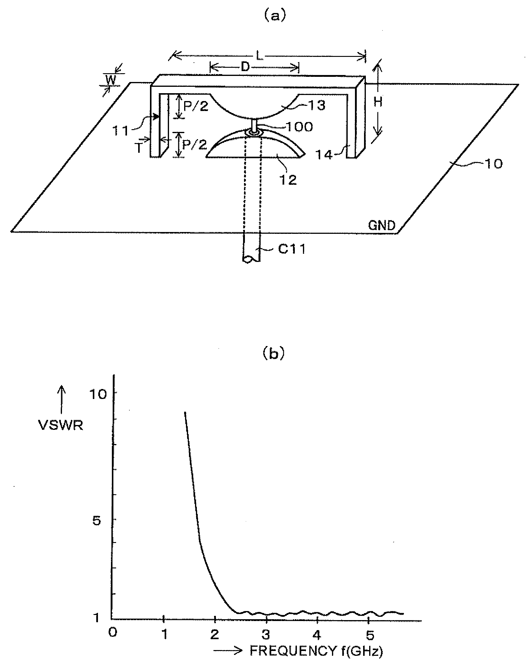
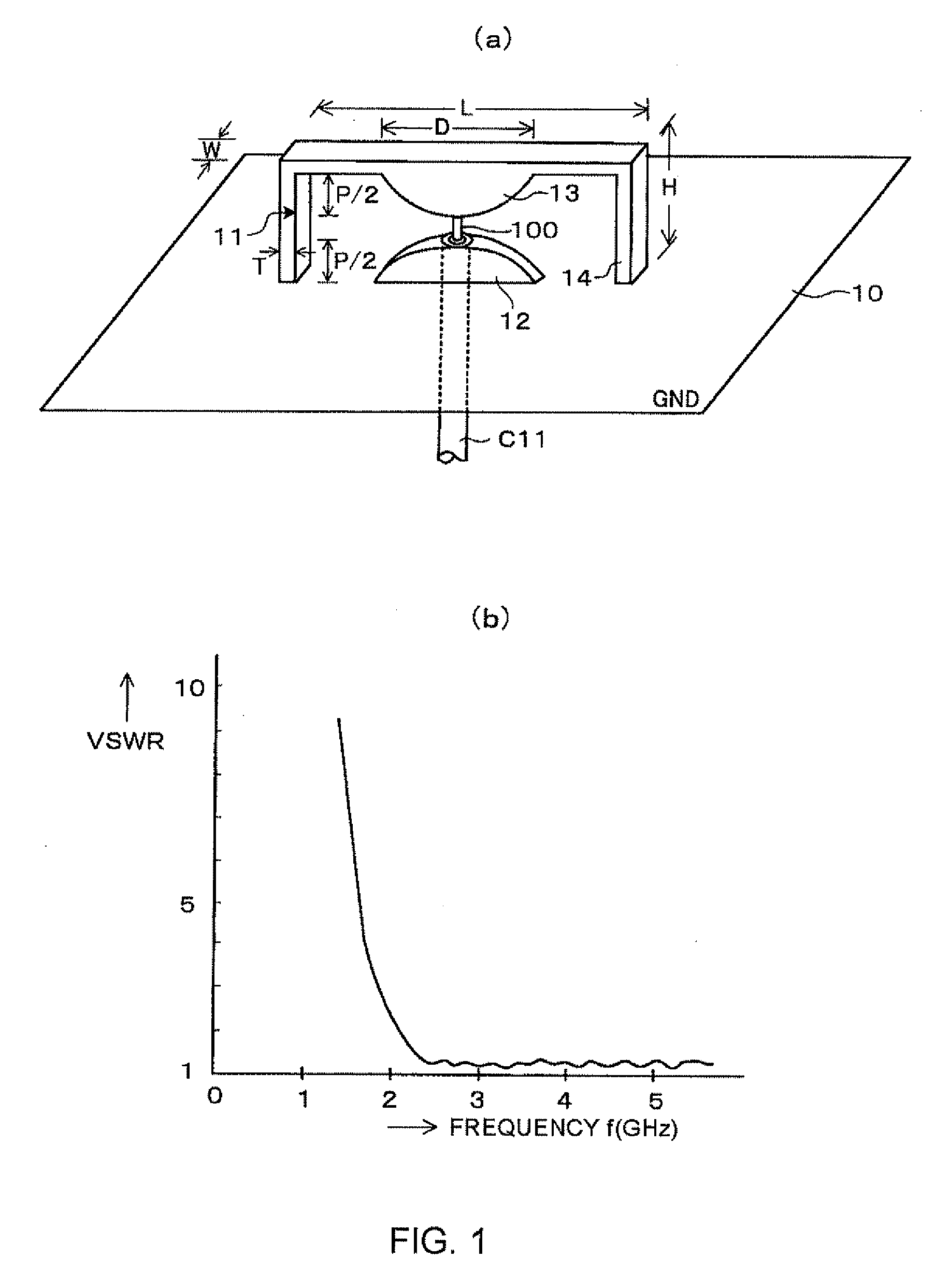
[0045]FIG. 1(a) is an external perspective view of a wide band antenna according to a first embodiment of the present invention and FIG. 1(b) is a graph showing VSWR characteristics. It should be noted here that the VSWR characteristics are one example of the antenna characteristics.

[0046]In the wide band antenna in this embodiment, a double (cylinder) ridge waveguide having a rectangular shape is cut in a tube axial direction at a predetermined thickness and one wide plane is used as the ground plane (hereinafter referred to as the “GND”). This wide band antenna performs an operation in conformity with a mode theory of the double ridge waveguide and includes an antenna element 11 and an auxiliary element 12. The antenna element 11 and the auxiliary element 12 are each made of a metal that is high in conductivity.

[0047]The antenna element 11 forms a shape of a ridge waveguide open cross-section structure together with the GND 10 when it is spread. In other words, the antenna element...

second embodiment

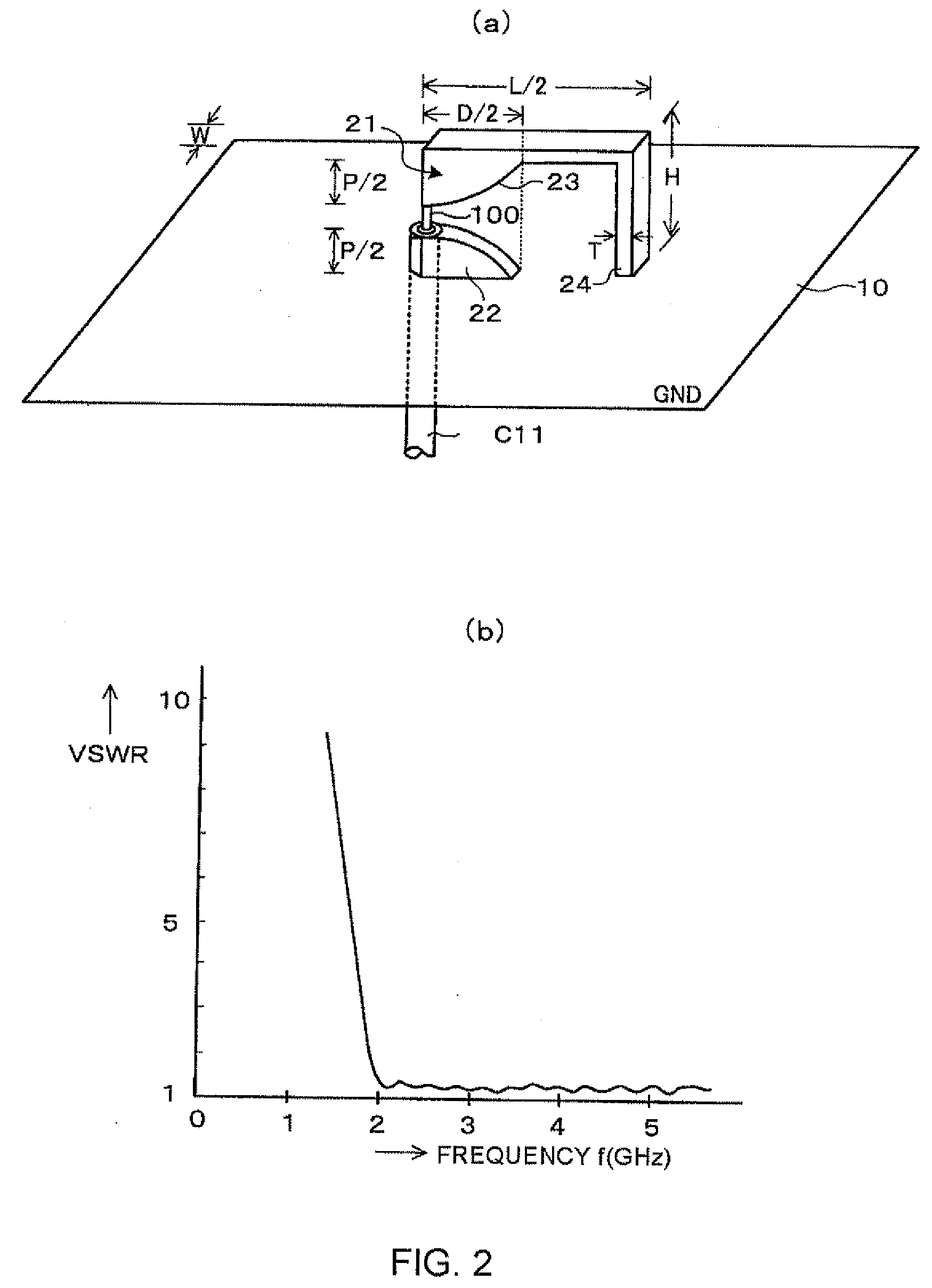
[0055]FIG. 2(a) is an external perspective view of a wide band antenna according to a second embodiment of the present invention and FIG. 2(b) is a graph showing VSWR characteristics.

[0056]As shown in FIG. 2(a) , the wide band antenna in this embodiment has a structure in which a right half of a cross section of a double ridge waveguide is cut out. In other words, the wide band antenna includes an antenna element 21, which has a ridge element portion 23 having a one base end structure obtained by cutting a ridge portion of an upper wide plane in a double ridge waveguide open cross-section structure in its height direction and a radiation element 24, and an auxiliary element 22.

[0057]The ridge element portion 23 acts in substantially the same manner as the ridge portion of the upper wide plane of the double ridge waveguide. The radiation element portion 24 acts in substantially the same manner as a wall of the double ridge waveguide and is used for electromagnetic wave radiation in t...

third embodiment

[0069]Next, an example of a form in the case where the present invention is carried out as a wide band antenna for UWB used in UWB communication will be described. It is assumed that the UWB communications is performed using the GPS, a wireless LAN, an on-vehicle radar, or the like at a communication frequency of 3.5 [GHz] or higher and a VSWR of 2.0 or less.

[0070]In order to facilitate antenna miniaturization, in this embodiment, a radiation element portion of an antenna element is set to form a predetermined angle with respect to a ridge element portion. For instance, FIG. 6 shows a wide band antenna for UWB communications that includes an antenna element 101 and an auxiliary element 102, with a first radiation element portion 104 and a second radiation element portion 105 of the antenna element 101 respectively extending from both base ends of a ridge element portion 103 vertically with respect to the ridge element portion 103 in mutually opposite directions. A tip end of the rid...


PUM


Abstract

There is provided a low-cost wide band antenna having an ultra-wide band and high performance. The wide band antenna includes an antenna element to form a shape of a ridge waveguide open cross-section structure together with GND (10) when it is spread. The antenna element has a ridge element portion (13) corresponding to the ridge portion of the ridge waveguide and a radiation element portion (14) corresponding to the wall of the ridge waveguide and extending from the ridge element portion (13) for electromagnetic wave radiation. Moreover, the antenna element has an opposing auxiliary element (12) having the same shape and structure as the ridge element portion (13). The radiation element portion (14) has an end arranged on the GND (10). The ridge element portion (13) has a tip end connected to a power supply terminal (100).

Description

TECHNICAL FIELD[0001]The present invention relates to a wide band communication system such as an ultra wide band (UWB) system, and a wide band antenna used in wireless systems operating in different frequency bands.BACKGROUND ART[0002]As antennas used in a wide band communication system, a multiple element antenna, a spiral antenna, a log periodic antenna, and the like are known.[0003]The multiple element antenna is an antenna configured to obtain wide-band antenna characteristics by combining many antenna elements each having slightly different frequency bands. This multiple element antenna has a superior characteristic as to wide-band property, but there is a need to combine multiple antenna elements, which leads to a difficulty to adjust a feeding impedance of each antenna element and adjust a resonance frequency thereof. The spiral antenna and the log periodic antenna are simple in structure but their overall volumes are large and, in addition, their directional characteristics...

Claims


Application Information

Patent Timeline
Patent Type & Authority Applications(United States)
IPC IPC(8): H01Q13/00
CPCH01Q7/00H01Q13/16H01Q13/10H01Q9/42H01Q5/50H01Q5/25
Inventor YANAGISAWA, WASUKEGE, JUNXIANG
Owner YOKOWO CO LTD
Why Eureka
Try Eureka