[0005]It is an object of the present invention to solve the above problem and to provide a vehicle and a lane mark detection device capable of increasing the detection accuracy by preventing an object other than a lane mark on a road from being incorrectly detected as a linear lane mark such as a white line when detecting a linear lane mark such as a white line from a road image.Means for Solving the Problem
[0009]In this case, the line component corresponding to an object other than the lane mark such as a wheel track on the road is not selected since it has a small evaluation value, and therefore it is possible to select a candidate for the line component corresponding to the lane mark with distinction between a linear lane mark such as a white line and an object other than the lane mark such as the wheel track on the road, even though such distinction is difficult to be made merely by the
edge extraction and the
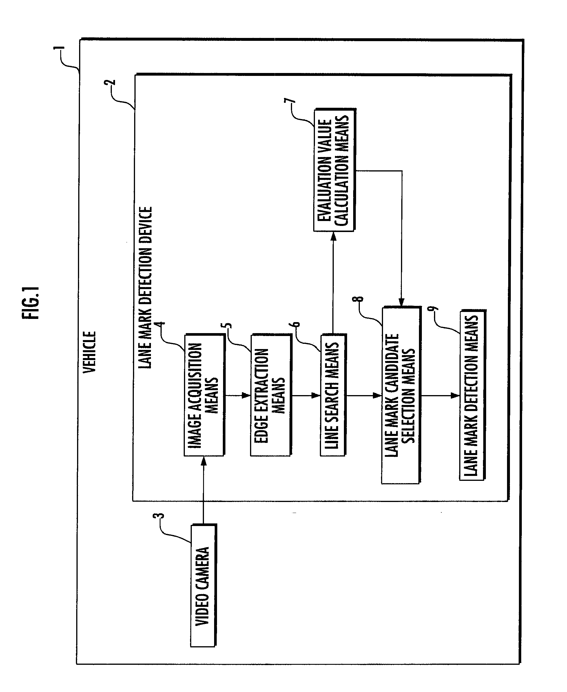
line search. Moreover, the lane mark detection means detects the lane mark by determining the line component corresponding to the lane mark from the selected line components, and therefore it is possible to prevent the object other than the lane mark such as the wheel track on the road from being incorrectly detected as a lane mark, thereby increasing the detection accuracy of the linear lane mark such as a white line. Particularly the use of the value obtained by filtering the
time series of the evaluation value enables a stable detection of the linear lane mark.
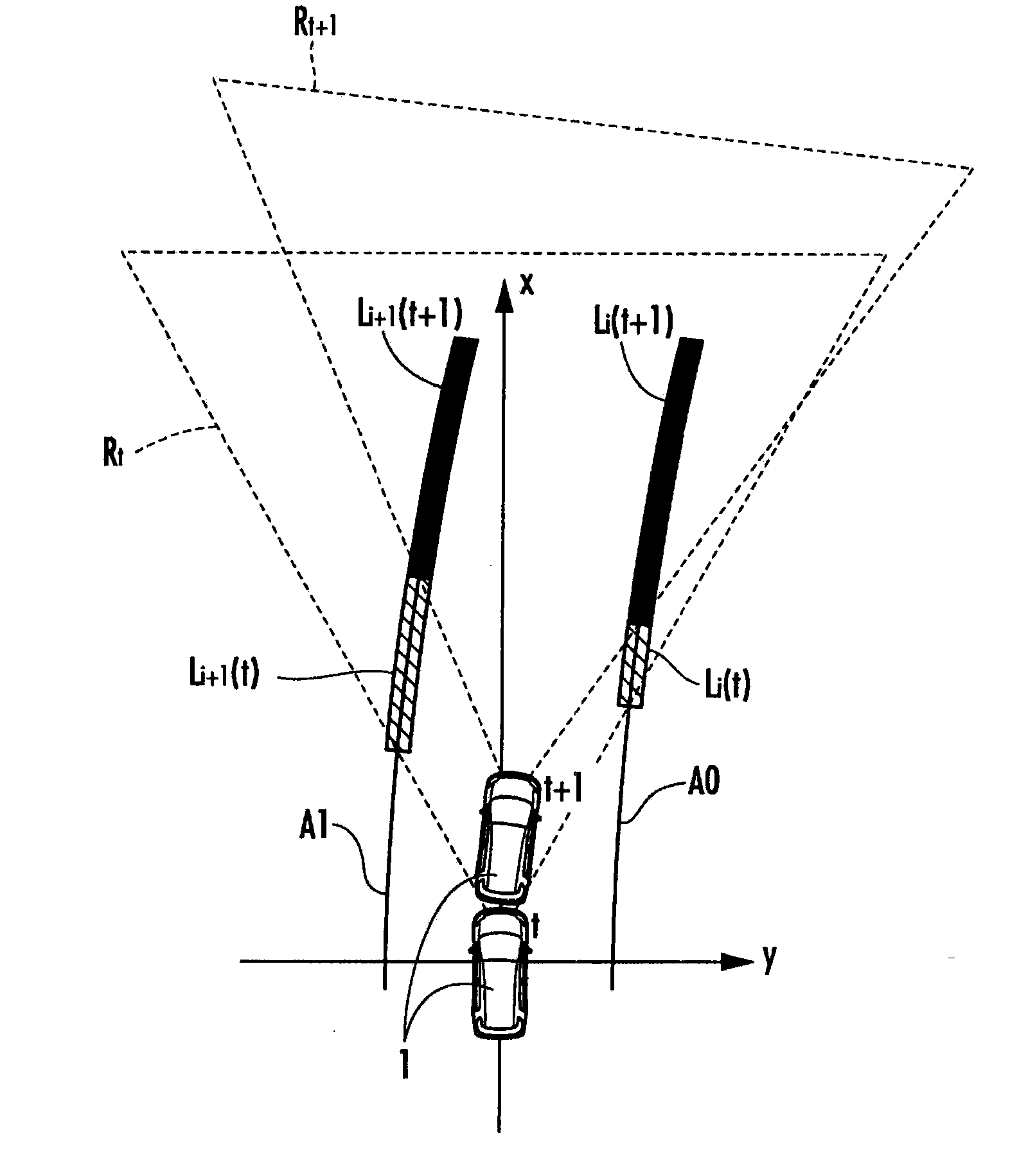
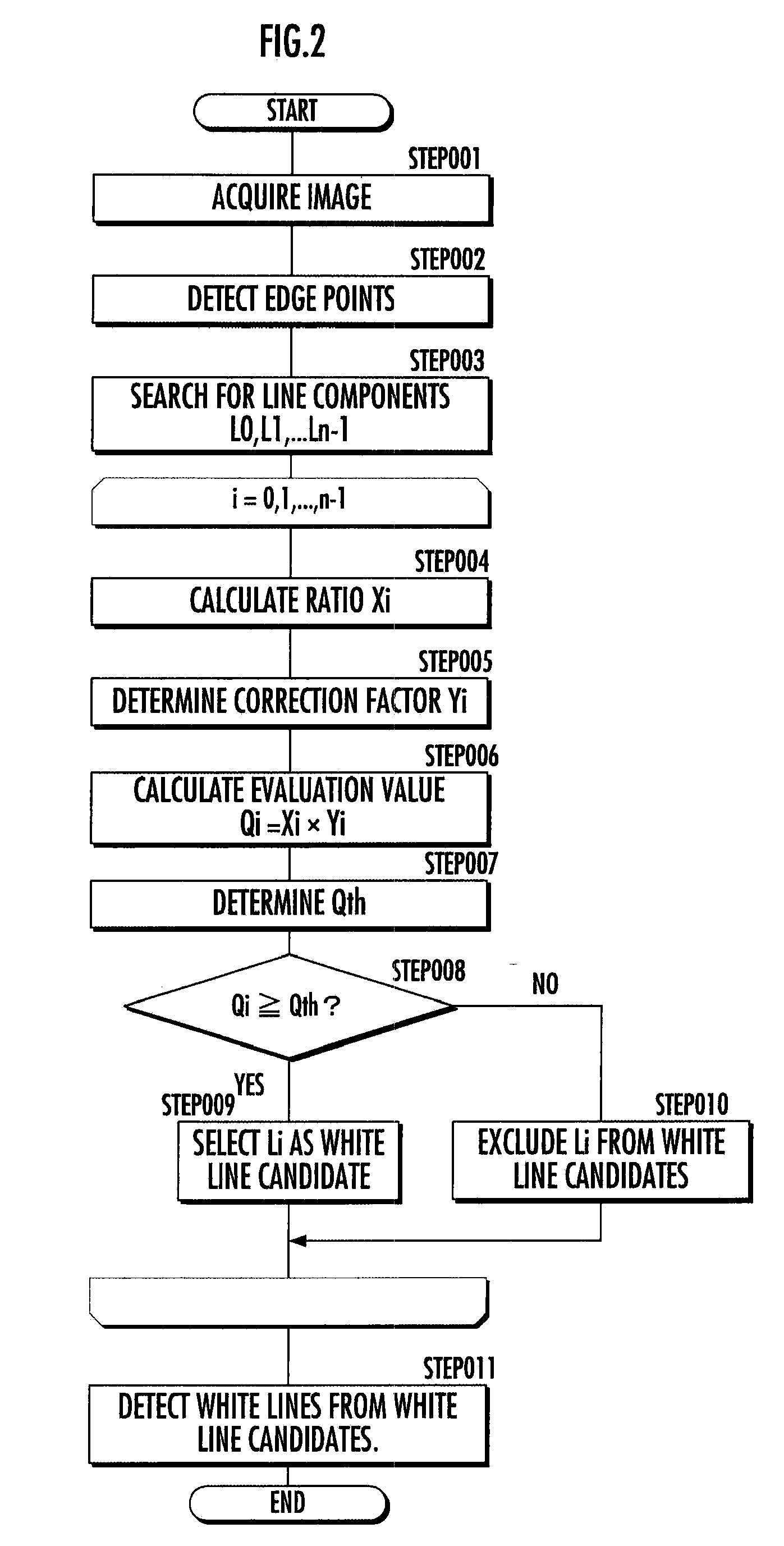
[0011]According thereto, the edge points constituting the line component corresponding to the linear lane mark such as a white line painted on the road are supposed to be extracted without a break in the image. On the other hand, the parts of the object other than the lane mark such as the wheel track on the road are scattered irregularly and the
road condition after rain and the light reflecting state vary within the
road surface. Consequently, the edge points constituting the corresponding line component are supposed to be often partially discontinuous in the image. Therefore, the evaluation value calculation means is capable of calculating the evaluation value enabling a distinction between the linear lane mark such as a white line and the object other than the lane mark such as the wheel track on the road by using the ratio between the number of edge points constituting the line component and the number of continuous edge points among the edge points.
[0015]According thereto, the greater the distance between the object to be detected such as the lane mark and the vehicle is, the smaller the object to be detected is in the image, which decreases the resolution for the
image processing per unit length of the object to be detected in the real space. Moreover, the
low resolution makes it difficult to determine that the edge points constituting the line component corresponding to the object to be detected are discontinuous in the image, and therefore it is supposed that the ratio between the number of edge points constituting the line component corresponding to the object other than a lane mark and the number of continuous edge points among the edge points easily increases. Therefore, the evaluation value calculation means calculates the evaluation value as the correction by multiplying the ratio between the number of edge points constituting the line component and the number of continuous edge points among the edge points by the correction factor set so as to decrease as the distance between the position of the line component in the real space and the vehicle increases. This inhibits the line component from being selected as a candidate for the line component corresponding to the lane mark due to a high evaluation value of the line component corresponding to the object other than the lane mark far from the vehicle.
[0017]According thereto, if the correction factor is increased in a situation where the distance between the object to be detected such as a lane mark and the vehicle is less than the first predetermined distance and the resolution for the
image processing per unit length of the object to be detected in the real space is sufficiently high, there is a possibility that the line component corresponding to the object other than the lane mark is selected as a candidate for the line component corresponding to the lane mark due to an increase in the evaluation value of the line component corresponding to the object other than the lane mark. Therefore, the evaluation value calculation means calculates the evaluation value with the correction factor set to the predetermined upper limit in the case where the distance between the position of the line component in the real space and the vehicle is less than the first predetermined distance. This prevents the correction factor from excessively increasing when calculating the evaluation value of the line component corresponding to the object to be detected near the vehicle and inhibits the line component corresponding to the object other than the lane mark located near the vehicle from being selected as a candidate for the line component corresponding to the lane mark due to a high evaluation value of the line component corresponding to the object other than the lane mark.
[0021]According thereto, in the case where the object to be detected such as a lane mark is located in an area far from the vehicle in the real space, the object to be detected is small in the image, which makes it difficult to determine that the edge points constituting the line component corresponding to the object to be detected are discontinuous in the image, and therefore it is supposed that the evaluation value of the line component corresponding to the object other than the lane mark easily increases. Therefore, the lane mark candidate selection means specifies the range corresponding to the area apart from the vehicle by the predetermined distance or more in the real space within the image and sets the threshold value for selecting the line component included in the range to the greater value than the threshold value for selecting the line component not included in the range. This enables a strict determination of the selection for an area apart from the vehicle by the predetermined distance or more and a loose determination of the selection for an area within the predetermined distance from the vehicle, thereby inhibiting the line component corresponding to the object other than the lane mark far from the vehicle from being selected as the candidate for the line component corresponding to the lane mark.

