Methods and apparatus for optical transmission of digital signals

a digital signal and optical transmission technology, applied in the field of optical communication, can solve the problems of severely limiting the reach of optical transmission spans, affecting the transmission speed of digital signals, and limiting the distance over which data may be transmitted in single-mode optical fibres before some form of regeneration is required, etc., to achieve high spectral efficiency, reduce the effect of chromatic dispersion of optical channels, and high spectral efficiency

Active Publication Date: 2009-07-02
MONASH UNIV
View PDF21 Cites 39 Cited by
  • Summary
  • Abstract
  • Description
  • Claims
  • Application Information

AI Technical Summary

Benefits of technology

[0019]performing a frequency domain equalisation of received data symbols included in each of said received data blocks to mitigate the effect of chromatic dispersion of the optical channel, thereby to recover the transmitted data symbols.
[0020]Accordingly, the method provides a transmitted optical signal having substantially only a single optical sideband, and which thereby enables the optical phase information to be preserved in an electrical signal generated at a corresponding optical detector, such that electronic dispersion compensation may be performed at a receiver. Furthermore, the use of block coding to generate the transmitted signal in combination with frequency domain equalisation techniques at a receiver, obviates the need for separate RF components at the transmitting or receiving ends to process signals carried on individual RF sub-carriers. The method is therefore highly scalable, providing high spectral efficiency, improved tolerance to dispersion, and simplified equalisation, or compensation, of the effects of chromatic dispersion in particular, without a corresponding scaling in the cost and / or complexity of apparatus at the transmitting or receiving ends.

Problems solved by technology

The distances over which data may be transmitted in single-mode optical fibres before some form of regeneration is required is limited by optical attenuation and pulse dispersion.
However, dispersion processes, including chromatic dispersion and polarisation mode dispersion (PMD), which lead to pulse broadening, remain a significant cause of distortion in such systems, which if not managed or compensated can severely limit the reach of optical transmission spans.
The problem presented by chromatic dispersion increases rapidly as the bit rate of optical data channels is increased.
In wavelength division multiplexed digital transmission systems in particular, it is not practical to reduce pulse broadening by employing optical fibre having a low or zero dispersion value near the transmission wavelength, because a low first order dispersion value is associated with increased distortion due to non-linear processes.
However, these methods are not without their drawbacks.
Accordingly, these components must be designed and / or configured to match the characteristics of the specific transmission spans in which they are installed, and they are not readily dynamically adaptable for use in different transmission spans, or in systems exhibiting varying total chromatic dispersion.
A significant obstacle to the implementation of electronic dispersion compensation within optical transmission systems is that most high-bandwidth optical systems employ intensity modulation at the transmitter, in combination with direct detection at the receiver.
Intensity modulation results in optical signals having two frequency sidebands disposed about a central optical carrier frequency, and direct detection of such signals results in a loss of the optical phase information which is required to enable the effects of dispersion generally, and chromatic dispersion in particular, to be compensated.
However, previously proposed electronic dispersion compensation techniques based on the use of OSSB transmission and / or RF sub-carrier multiplexing suffer from a number of remaining limitations.
Firstly, the quality and cost of the RF components, including RF filters, mixers and so forth, limit the number of RF sub-carriers that may be employed, and the spectral efficiency of the sub-carrier multiplexing.
Furthermore, similar limitations and / or costs are imposed at the receiver, where the RF sub-carriers must be demultiplexed and compensated, or equalised, independently.
Additionally, the systems proposed to date have exhibited comparatively poor optical power efficiency.

Method used


Image

  • Methods and apparatus for optical transmission of digital signals
  • Methods and apparatus for optical transmission of digital signals
  • Methods and apparatus for optical transmission of digital signals

Examples


Embodiment Construction

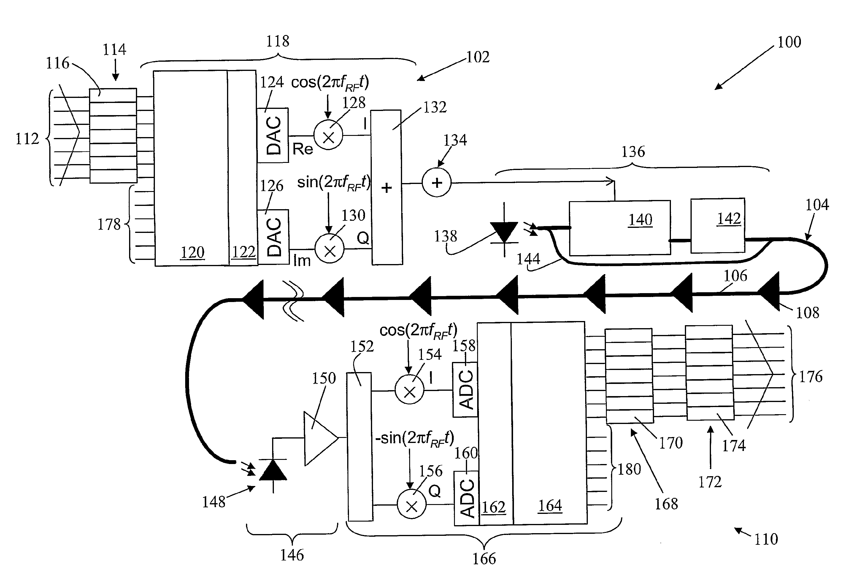
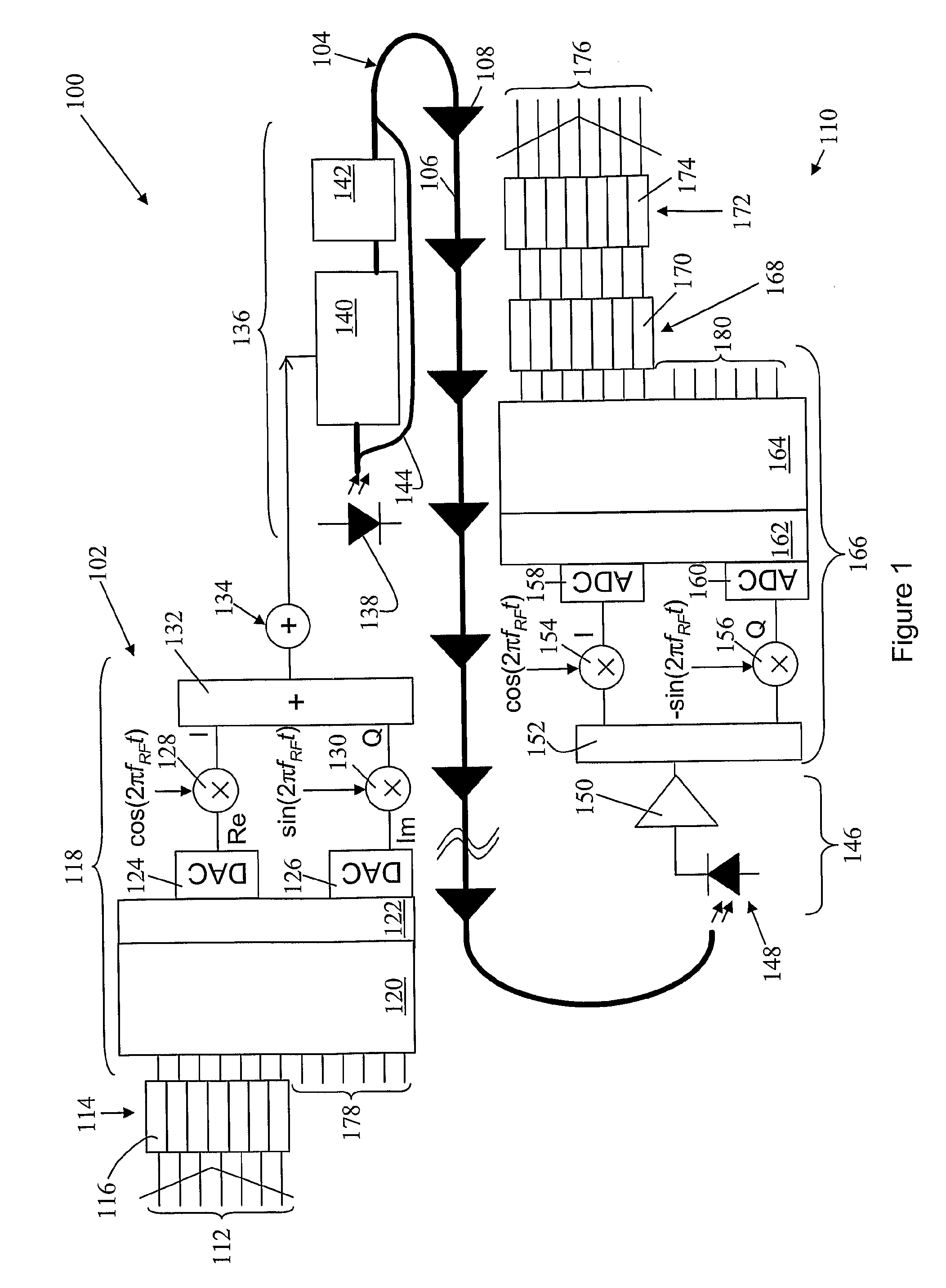
[0081]Turning first to FIG. 1, there is shown schematically a system 100 for communicating digital information over a long span of dispersive single-mode fibre according to an embodiment of the present invention.

[0082]The exemplary system 100 includes apparatus 102 for generating an optical signal bearing digital information for transmission over amplified single-mode fibre span 104. The transmission span 104 may generally include a plurality of individual single-mode fibre sections, eg 106, with loss-compensating amplifiers, eg 108, inserted therebetween to overcome losses in signal power resulting from the attenuation of the single-mode fibre links.

[0083]The system 100 also includes receiving apparatus 110 for receiving the digital information transmitted from transmitting apparatus 102 over fibre span 104.

[0084]Digital information for transmission over fibre span 104 is input to the transmitter 102 via the parallel input port 112. The input digital information is processed within...


PUM


Abstract

A system (100) for transmitting digital information includes a transmitting apparatus (102) for generating an optical signal bearing digital information, a dispersive optical channel (104), and a receiving apparatus (110) for receiving the optical signal. The dispersive optical channel (104) is disposed to convey the optical signal from the transmitting apparatus (102) to the receiving apparatus (110). The transmitting apparatus includes an encoder (114) for encoding digital information into a series of blocks, each including a plurality of data symbols corresponding with one or more bits of digital information. A signal generator (118) generates a time-varying signal corresponding with each of said blocks. An optical transmitter (136) is arranged to apply the time-varying signal to an optical source (138) to produce an optical signal which includes an optical carrier and substantially only a single information bearing optical sideband in an optical frequency domain, the sideband corresponding with the time-varying signal. The receiving apparatus (110) includes an optical detector (146) for detecting the optical signal to produce a corresponding received time-varying electrical signal. The receiver further includes means (166) for generating a series of received data blocks from the time-varying electrical signal. An equaliser (168) performs an equalisation of received data symbols included in each data block to mitigate the effect of dispersion of the optical channel, thereby enabling the transmitted data symbols to be recovered.

Description

FIELD OF THE INVENTION[0001]The present invention relates generally to optical communications, and more particularly to methods and apparatus for generation of optical signals for transmission over long distances via optical channels, and especially optical fibres, which exhibit high levels of total chromatic dispersion.BACKGROUND OF THE INVENTION[0002]Optical transmission, in which an information signal is modulated onto an optical carrier, is widely employed in modern communications systems. In particular, wide area communications networks employ long-haul transmission links using single mode optical fibres for the transmission of digital information at very high bit rates, using one or more optical carriers, or wavelengths, over each fibre. The distances over which data may be transmitted in single-mode optical fibres before some form of regeneration is required is limited by optical attenuation and pulse dispersion. The advent of practical optical amplifiers has substantially el...

Claims


Application Information

Patent Timeline
Patent Type & Authority Applications(United States)
IPC IPC(8): H04J14/08
CPCH04B10/2513H04B10/5165H04B10/541H04B10/556H04B10/548H04B10/5563H04B10/6971H04N7/22H04B10/5561H04B10/25H04B10/50H04B10/60
Inventor LOWERY, ARTHUR JAMESARMSTRONG, JEAN
Owner MONASH UNIV
Why Eureka
Try Eureka