Fan Frame Structure

a fan frame and frame technology, applied in the direction of machines/engines, stators, liquid fuel engines, etc., can solve the problems of high cost of the fan frame structure, structural strength and quality problems, and inventory management problems, so as to reduce manufacturing costs, save mold costs, and enhance quality

Inactive Publication Date: 2009-07-02
SUNONWEALTH ELECTRIC MACHINE IND
View PDF2 Cites 15 Cited by
  • Summary
  • Abstract
  • Description
  • Claims
  • Application Information

AI Technical Summary

Benefits of technology

[0008]The present invention solves this need and other problems in the field of fan frame structures by providing a fan frame structure including a plastic casing and a metal fixing frame. The plastic casing and the metal fixing frame are provided for an axial flow fan or a blower fan. A fan frame structure made of different materials is provided for reducing the manufacturing costs, saving the costs for molds, enhancing quality and allowing easy inventory management. Furthermore, the metal fixing frame provides sufficient structural strength and desired heat dissipating effect.

Problems solved by technology

Using metal material results in high costs of the fan frame structure.
On the other hand, the support arms 14 of the fan frame structure made of plastic material are fragile and, thus, liable to break, leading to problems in structural strength and quality.
Furthermore, conventional fan frames have various specifications to meet the requirements of assembly of fan motors of differing powers, leading to problems in inventory management due to various types of products or demand of a large warehouse or space.

Method used


Image

  • Fan Frame Structure
  • Fan Frame Structure
  • Fan Frame Structure

Examples


first embodiment

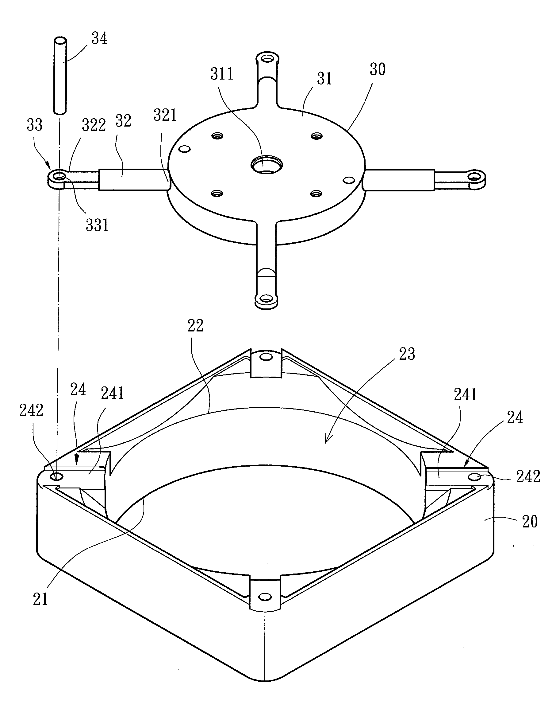
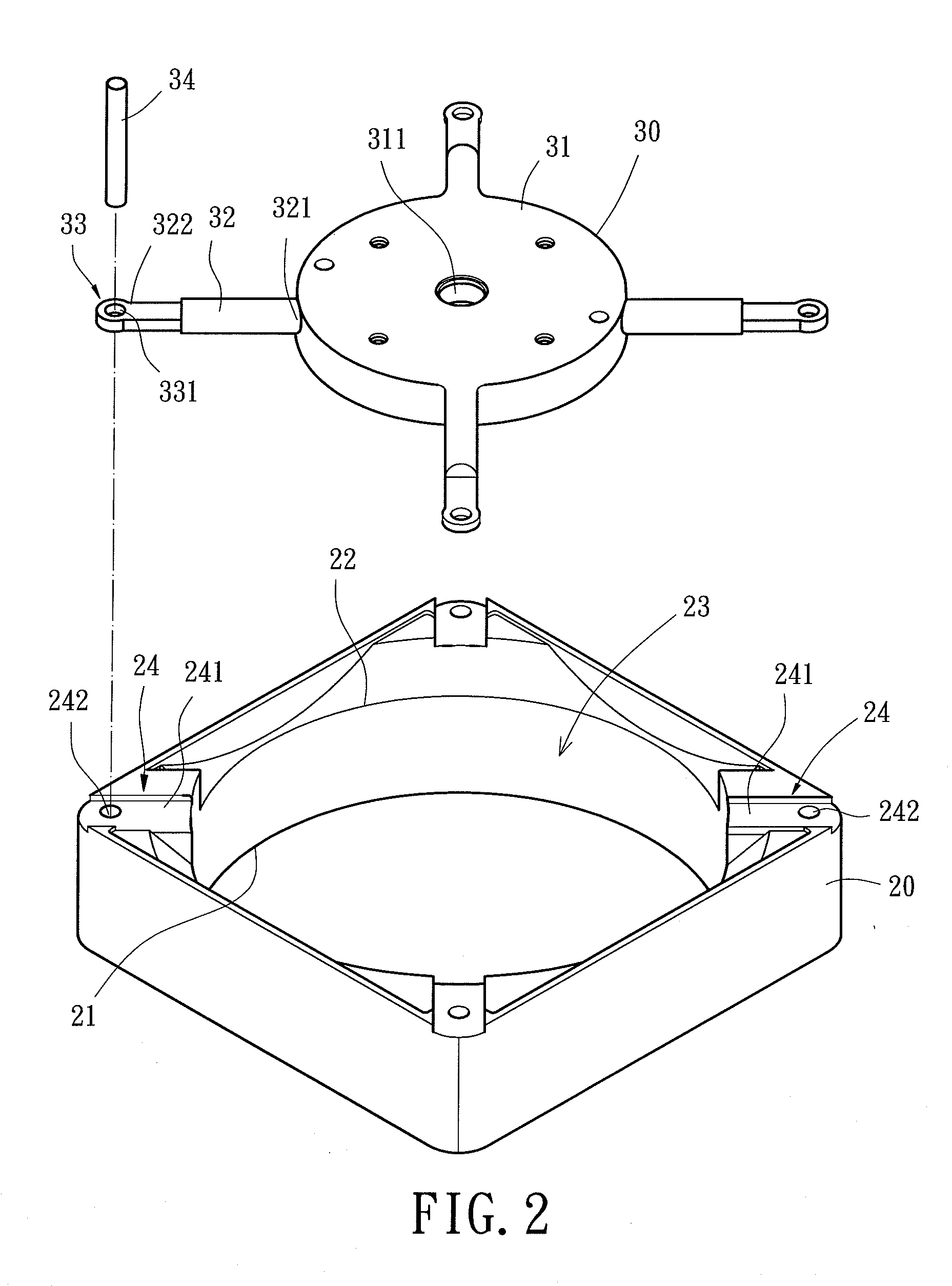
[0036]A fan frame structure of a first embodiment according to the preferred teachings of the present invention is shown in FIG. 2 of the drawings. According to the preferred form shown, the fan frame structure is provided for an axial flow fan. The fan frame structure includes a plastic casing 20 and a metal fixing frame 30. Specifically, the plastic casing 20 includes an air inlet 21 in a top side thereof and an air outlet 22 in a bottom side thereof parallel to and spaced from the top side. The plastic casing 20 defines an accommodation space 23 in communication with the air inlet 21 and the air outlet 22. The bottom side of the plastic casing 20 includes a plurality of first fixing portions 24 at corners of the plastic casing 20. In the most preferred form shown, each first fixing portion 24 includes a groove 241 in each corner of the bottom side of the plastic casing 20. Each groove 241 includes a bottom wall having a hole 242 that is preferably a through-hole.

[0037]According t...

second embodiment

[0039]FIGS. 3-6 show a fan frame structure of a second embodiment according to the preferred teachings of the present invention. In the preferred form shown, the plastic casing 40 includes an air inlet 41 in a top side thereof and an air outlet 42 in a bottom side thereof. The plastic casing 40 defines an accommodation space 43 in communication with the air inlet 41 and the air outlet 42. The bottom side of the plastic casing 40 includes a plurality of first fixing portions 44 at corners of the plastic casing 40. In the most preferred form shown, the plastic casing 40 is integrally formed by injection molding to form the first fixing portions 44 that envelope predetermined portions of the metal fixing frame 50.

[0040]The metal fixing frame 50 includes a base 51 having a shaft tube seat 511 in a center thereof. The shaft tube seat 511 can be in the form of a hole, a tube, or other structure capable of coupling with a shaft. A plurality of support arms 52 extend radially outward from a...

third embodiment

[0043]FIGS. 7-9 show a fan frame structure of a third embodiment according to the preferred teachings of the present invention. In the preferred form shown, the fan frame structure is provided for a blower fan and includes a plastic casing 60 and a metal fixing frame 70. In the preferred form shown, the plastic casing 60 includes an air inlet 61 in a top side thereof and an air outlet 62 in a lateral side thereof perpendicular to the top side. The plastic casing 60 defines an accommodation space 63 in communication with the air inlet 61 and the air outlet 62. A bottom side of the plastic casing 60 includes a peripheral edge having a plurality of first fixing portions 64. In the most preferred form shown, the plastic casing 60 is integrally formed by injection molding to form the first fixing portions 64 enveloping predetermined portions of the metal fixing frame 70.

[0044]According to the preferred form shown, the metal fixing frame 70 includes a base 71 having a shaft tube seat 711 ...


PUM


Abstract

A fan frame structure includes a plastic casing and a metal fixing frame. The plastic casing and the metal fixing frame are provided for an axial flow fan or a blower fan. The plastic casing includes a bottom having a plurality of first fixing portions. The metal fixing frame includes a base having a base with a shaft tube seat in a center thereof. The base includes a plurality of second portions each engaged with one of the first fixing portions. Since the plastic casing is made of inexpensive plastic material, the manufacturing costs are cut. The metal fixing frame provides sufficient structural strength and desired heat dissipating effect.

Description

CROSS REFERENCE TO RELATED APPLICATION[0001]This is a continuation-in-part application of U.S. patent application Ser. No. 12 / 003,530 filed on Dec. 28, 2007.BACKGROUND OF THE INVENTION[0002]1. Field of the Invention[0003]The present invention relates to a fan frame structure and, more particularly, to a fan frame structure including a plastic casing and a metal fixing frame.[0004]2. Description of the Related Art[0005]FIG. 1 shows a conventional fan frame structure including a frame 10 having a central accommodation space 11 receiving a bottom base 12. Formed at a center of the bottom base 12 is a shaft tube seat 13, allowing mounting of a fan motor and fan blades to the bottom base 12 in the accommodation space 11. A plurality of support arms 14 are interconnected between the bottom base 12 and an inner periphery of the accommodation space 11. The frame 10 is integrally formed with the bottom base 12.[0006]The conventional fan frame structure is integrally formed by die casting wit...

Claims


Application Information

Patent Timeline
Patent Type & Authority Applications(United States)
IPC IPC(8): F01D25/28
CPCF04D29/646F04D29/522
Inventor HORNG, ALEX
Owner SUNONWEALTH ELECTRIC MACHINE IND
Why Eureka
Try Eureka