Method of forming cooling holes and turbine airfoil with hybrid-formed cooling holes

a technology of turbine airfoil and cooling hole, which is applied in the direction of machines/engines, continuous combustion chambers, waterborne vessels, etc., can solve the problems of slow edm hole formation, difficult and expensive machine into turbine airfoils and other parts, and tens of seconds to over a minute per hole, so as to reduce the time per shape

Inactive Publication Date: 2009-07-02
GENERAL ELECTRIC CO
View PDF9 Cites 52 Cited by
  • Summary
  • Abstract
  • Description
  • Claims
  • Application Information

AI Technical Summary

Benefits of technology

[0012]A combination EDM and laser processes is used to form the film cooling holes in turbine airfoils, leveraging the throughput and quality strengths of both technologies. A laser system that can mill the shaped section of the hole is used to reduce the time per shape. The laser is capable of machining/micro-machining the shaped section of the hole

Problems solved by technology

As turbine designs have become more complex and efficient, it has become more common for these engines to rely on complex, 3-dimensional, film cooling patterns to distribute cooling air across airfoil bodies to minimize thermal stress on the component in engine operation.
These transitional holes are difficult and expensive to machine into turbine airfoils and other parts requiring critical cooling airflow.
However, EDM hole formation is slow, typically entailing tens of seconds to over a minute per hole drilled.
However

Method used


Image

  • Method of forming cooling holes and turbine airfoil with hybrid-formed cooling holes
  • Method of forming cooling holes and turbine airfoil with hybrid-formed cooling holes
  • Method of forming cooling holes and turbine airfoil with hybrid-formed cooling holes

Examples


Embodiment Construction

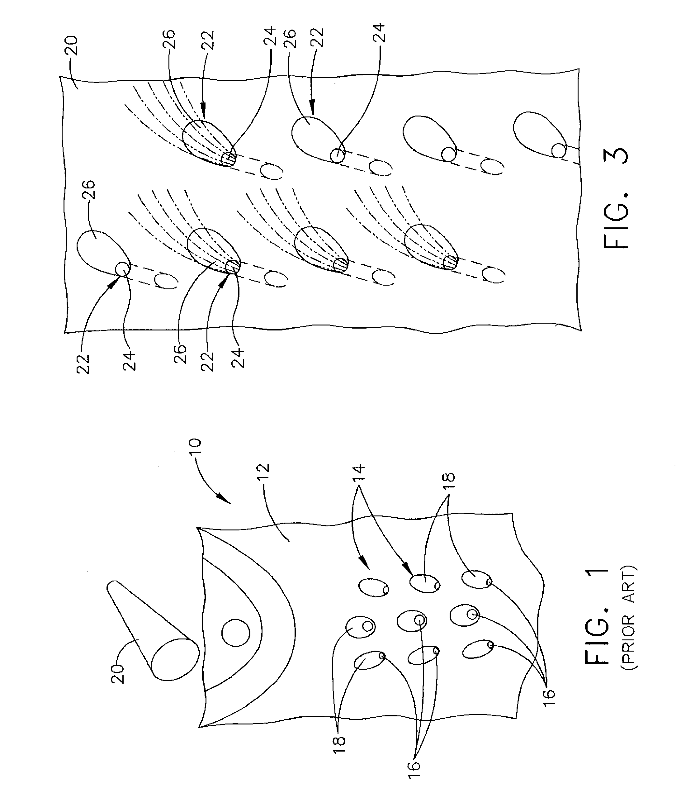
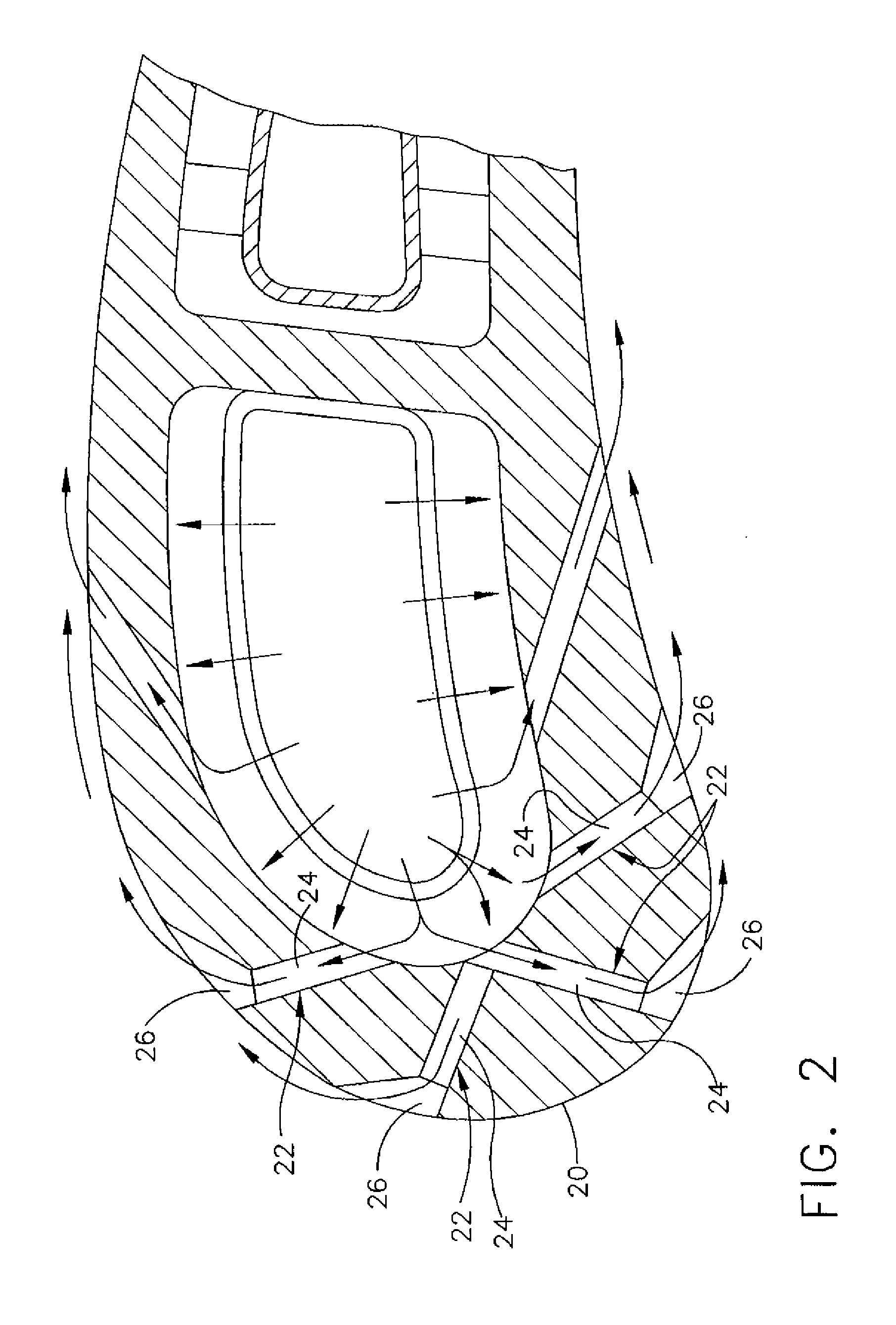
[0027]Referring now specifically to the drawings, examples of airfoils with leading edge cooling holes are shown in FIGS. 1-3. FIG. I shows an airfoil 10 having a leading edge 12 having cooling holes 14. The holes 14 include a cylindrical metering section 16 and a conical diffuser section 18 that communicates with the holes 14 in the surface of the leading edge. The diffuser section 18 has an inner wall that forms an endless wall surface. The laser is used to form the diffuser section 18 of the holes 14, and a EDM tool is used to form the metering section 16 of the holes 14. Ordinarily, the laser will first be used to form the blind diffuser section 18, and then the EDM tool will be used to extend the hole through to the cooling circuit by forming the cylindrical metering section 16. However, the EDM tool may be used to first form a cylindrical hole extending through the leading edge 12, followed by enlargement of the outer portion of the cylindrical hole by the laser to form the di...


PUM

PropertyMeasurementUnit
Radiusaaaaaaaaaa

Abstract

A method of forming a cooling hole in a workpiece that includes the steps of laser-forming a blind, inwardly-tapering transition opening into a first side of the workpiece, and EDM-forming a generally cylindrical through hole to a second, opposing side of the workpiece communicating with the inwardly-tapering transition opening to form a through cooling hole communicating with the first and second sides of the workpiece. An airfoil having cooling holes formed by use of both laser and EDM is also disclosed.

Description

TECHNICAL FIELD AND BACKGROUND OF THE INVENTION[0001]This invention relates to a method of forming cooling holes, and a turbine airfoil with cooling holes formed by use of two distinct hole-forming techniques.[0002]In a gas turbine engine, air is compressed in a compressor, mixed with fuel and ignited in a combustor for generating hot combustion gases which flow downstream through one or more stages of turbine nozzles and blades. The nozzles include stationary vanes followed in turn by a corresponding row of turbine rotor blades attached to the perimeter of a rotating disk. The vanes and blades have correspondingly configured airfoils which are hollow and include various cooling circuits and features which receive a portion of air bled from the compressor for providing cooling against the heat from the combustion gases.[0003]The turbine vane and blade cooling art discloses various configurations for enhancing cooling and reducing the required amount of cooling air in order to increa...

Claims


Application Information

Patent Timeline
IPC IPC(8): F01D5/18B23H5/00B23H9/10B23K26/38
CPCB23H9/10B23K26/0093B23K26/385B23K26/388B23K2201/001F05D2230/13F01D5/186F23R2900/00018F23R2900/03042F05D2260/202F05D2230/12B23P2700/06B23K26/389B23K2101/001
Inventor CROW, JOHNZURAWKA, JOHNDANOWSKI, MICHAELPEREZ, CARLOS WALBERTO
Owner GENERAL ELECTRIC CO
Why Eureka
Try Eureka