Low thermal and radiation conductivity coating

Active Publication Date: 2009-07-02
GENERAL ELECTRIC CO
View PDF4 Cites 3 Cited by
  • Summary
  • Abstract
  • Description
  • Claims
  • Application Information

AI Technical Summary

Benefits of technology

[0007]An advantage of the present invention is that it is opaque to infrared radiation (IR). Thus, IR cannot penetrate below the outer portion to serve as a heat source for the underlying substrate, causing further heating of the substrate. IR is effectively eliminated as a heat source of the substrate by the outer portion.
[0008]While the outer portion protects the underlying portions from IR as a heat source, the performance portion of the coating system of the present invention advantageously provides thermal protection by performing as

Problems solved by technology

Thus, IR cannot penetrate below the outer portion to serve as a heat sour

Method used


Image

  • Low thermal and radiation conductivity coating
  • Low thermal and radiation conductivity coating
  • Low thermal and radiation conductivity coating

Examples


Example

EXAMPLE I

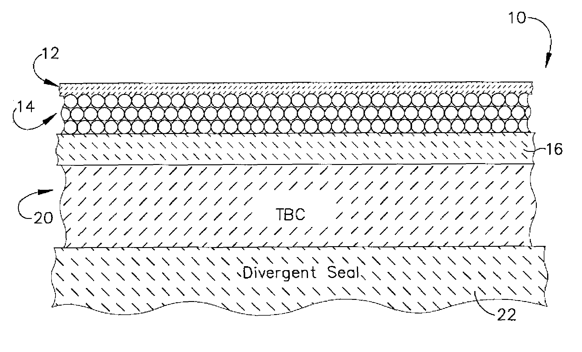
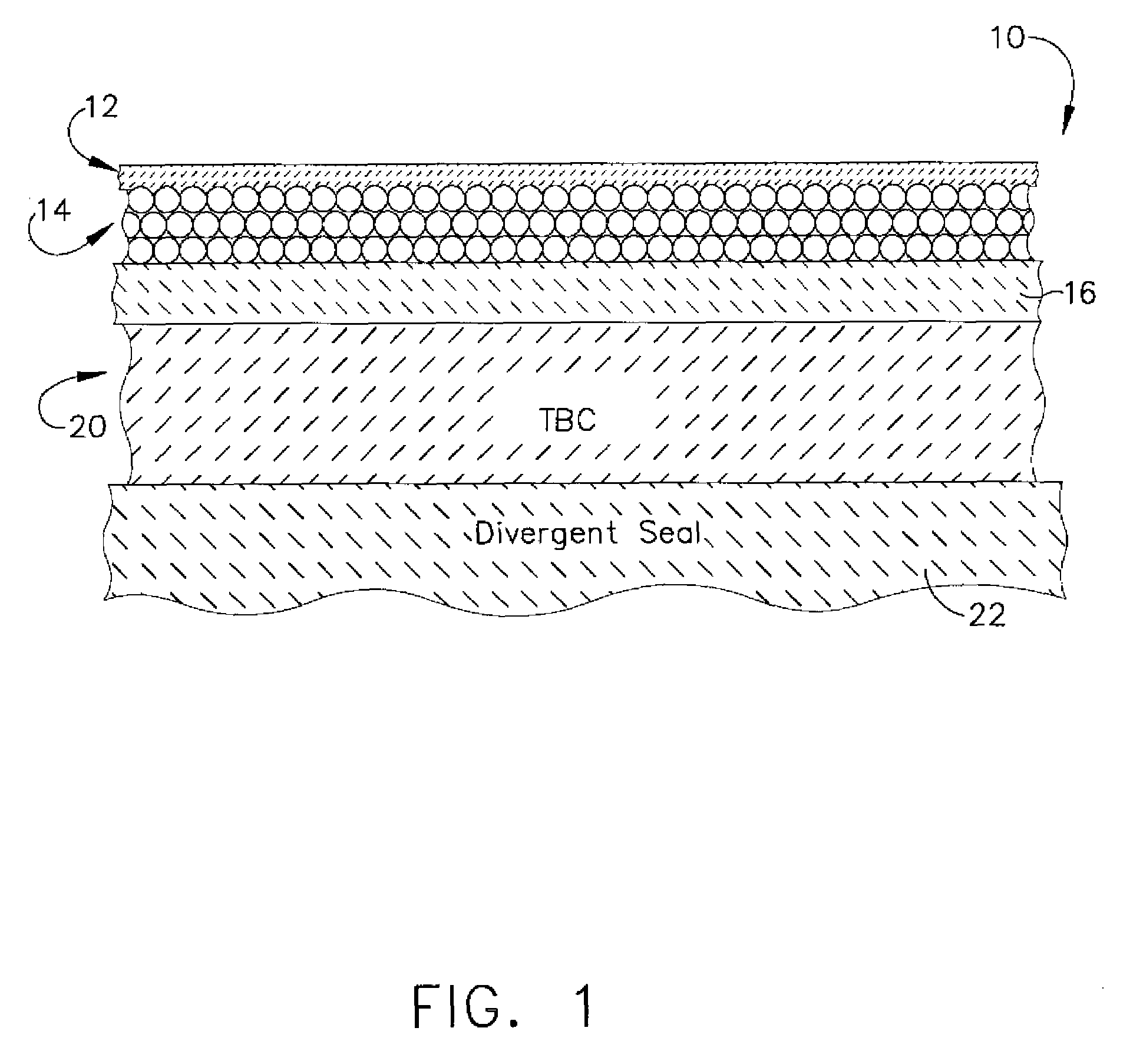
[0020]A coating system 10 of the present invention was prepared by fabricating an IR interactive portion 12 as a tape, a performance portion as a tape and a compliance portion as a tape.

[0021]The compliance portion 16 was prepared as a slurry by mixing about 75 g of reagent grade ethyl alcohol, about 30 g of silicone SR-355, and about 9.0 g of Merpol A in a sealed container that includes 1 inch alumina ball media and mixing until the silicone is dispersed. About 115.7 g of alumina A14 and about 84.3 g of alumina SM-8 were added to the container, resealed and milled on a ball mill for about 1-2 hours. Next, about 7 g of DBP was added to the container, which was resealed and milled on a ball mill for about 8-13 hours. Finally, about 14.0 g of B79 was added to the container, which was resealed and milled for about 2 hours to form the final slurry. The slurry was then tape cast onto a silicone-coated Mylar® tape and doctor-bladed to a tape thickness of about 8 mils. The tape wa...

Example

EXAMPLE 2

[0025]A coating system 10 of the present invention was prepared by fabricating an IR interactive portion 12 as a tape, a performance portion as a tape and a compliance portion as a tape. The compliance portion and the performance portion were prepared as set forth in Example 1.

[0026]Each of the compositions comprising the different portions is prepared by forming a slurry. The portions can be applied by any available technique including spraying, casting or forming a tape, which involves tape casting. Although each of the portions 12, 14 and 16, may have a uniform composition, more flexibility in obtaining desirable mechanical properties and thermal performance can be obtained by grading the portions, and in particular by grading portions 12 and 14. This means that the compositions across the portions will vary slightly in a predetermined fashion, thereby achieving the desired gradation.

[0027]A high-E IR interactive portion 12 was prepared as a slurry by mixing about 75 g o...


PUM

PropertyMeasurementUnit
Fractionaaaaaaaaaa
Fractionaaaaaaaaaa
Fractionaaaaaaaaaa

Abstract

A coating system that includes a plurality of portions, each portion comprising one or more layers. The coating system includes an outer portion, which is an infrared radiation (IR) interaction portion, that dissipates incident (IR). Underlying this outer portion is a performance portion. The performance portion comprises at least one layer that includes microspheres. Between the substrate and performance portion is a compliance portion. The compliance portion comprises at least one layer of high temperature material that has a coefficient of thermal expansion (CTE) intermediate the performance layer and the substrate. The compliance portion thus reduces any high temperature thermal mismatch between the substrate and the performance portion.

Description

FIELD OF THE INVENTION[0001]The present invention is directed to a coating that reduces the thermal loading on parts exposed to hot temperatures, and in particularly, for components such as secondary seals in a gas turbine engines having augmentationBACKGROUND OF THE INVENTION[0002]High performance engines for military aircraft utilize augmentation, sometimes referred to as afterburners, for increased thrust. This augmentation injects additional fuel into the exhaust and ignites the fuel, thereby providing additional thrust. The components utilized to provide this thrust are located in the exhaust path of the engine, such as the spray bars and the igniters, and are exposed to the exhaust gases. Of course, the components downstream of the spray bars and igniters, such as the secondary seals, are exposed to elevated temperatures even higher than the exhaust temperatures as a result of the injection of additional fuel into the exhaust stream.[0003]To protect the components in the exhau...

Claims


Application Information

Patent Timeline
IPC IPC(8): B32B17/06
CPCC03C14/004F02K1/825Y02T50/67F05D2230/313F05D2300/504Y10T428/25F05D2300/50212F05D2300/603F05D2300/50211C23C28/042C23C28/048F05D2230/90Y10T428/31612Y10T428/31663Y02T50/60
Inventor IVKOVICH, DANIEL P.STOWELL, WILLIAM RANDOLPHSENILE, DARRELLRENTZ, THOMAS W.ACKERMAN, JOHN F.
Owner GENERAL ELECTRIC CO
Why Eureka
Try Eureka