
Method and a machine for ex situ fabrication of low and medium integration biochip arrays

a biochip array and ex situ fabrication technology, applied in the field of biochips, can solve the problems of high cost, limited application to studies with high added value, and complex and expensive studies, and achieve the effect of high viscosity

Inactive Publication Date: 2009-07-02
ECOLE CENT DE LYON
View PDF7 Cites 4 Cited by
  • Summary
  • Abstract
  • Description
  • Claims
  • Application Information

AI Technical Summary

Benefits of technology

The invention provides a new technique for fabricating biochip arrays with millions of probes using a microprojection device. The technique is efficient, fast, and cost-effective, making it ideal for industry needs. The device uses a tank of reagent and a source of gas to project the reagent onto a substrate. The method involves controlling the actuator to isolate the tank from the reagent while the reagent is under pressure, and then using the reagent to form spots on the substrate. The device can form multiple spots simultaneously and can calibrate the amount of reagent projected. The invention also includes a machine for carrying out the method and a removable module for easy installation and replacement.

Problems solved by technology

High integration biochips are used for studies that are very complex and expensive.
Such very lengthy development leads to high costs, which limits applications to studies having high added value, for example studying the side effects of medicines.
The tank has an orifice that is always open, so problems arise of probe conservation due to possible evaporation and contact with the atmosphere.
Furthermore, microprojection using a device of this type is limited to a maximum volume of the order of 4 picoliters (pl) to 30 pl for a tank having a volume of milliliter (ml) order, which means that operations of decontamination by replacing the probe-containing solution with a cleaning liquid are not easy, nor are emptying operations, given the small flow rate that can be achieved.
Finally, piezoelectric type microprojection devices require control devices that are complex and difficult to develop.

Method used


Image

  • Method and a machine for ex situ fabrication of low and medium integration biochip arrays
  • Method and a machine for ex situ fabrication of low and medium integration biochip arrays
  • Method and a machine for ex situ fabrication of low and medium integration biochip arrays

Examples


Embodiment Construction

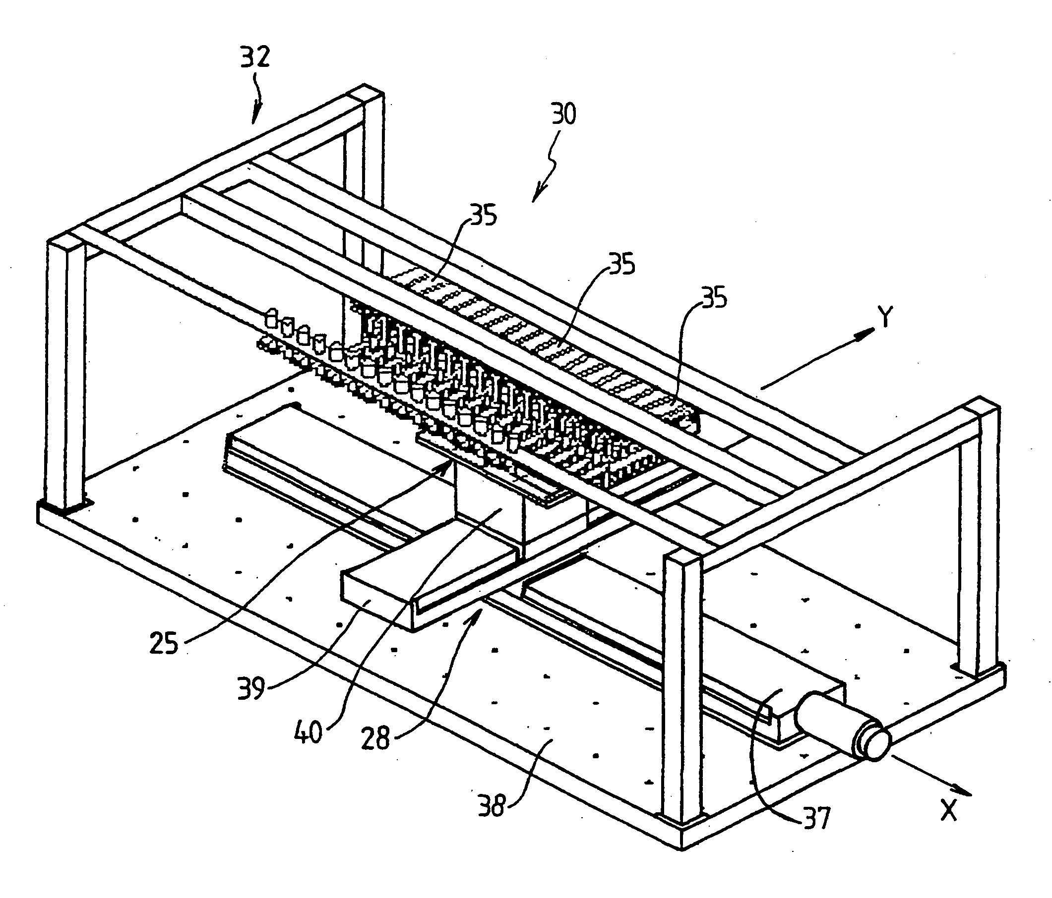
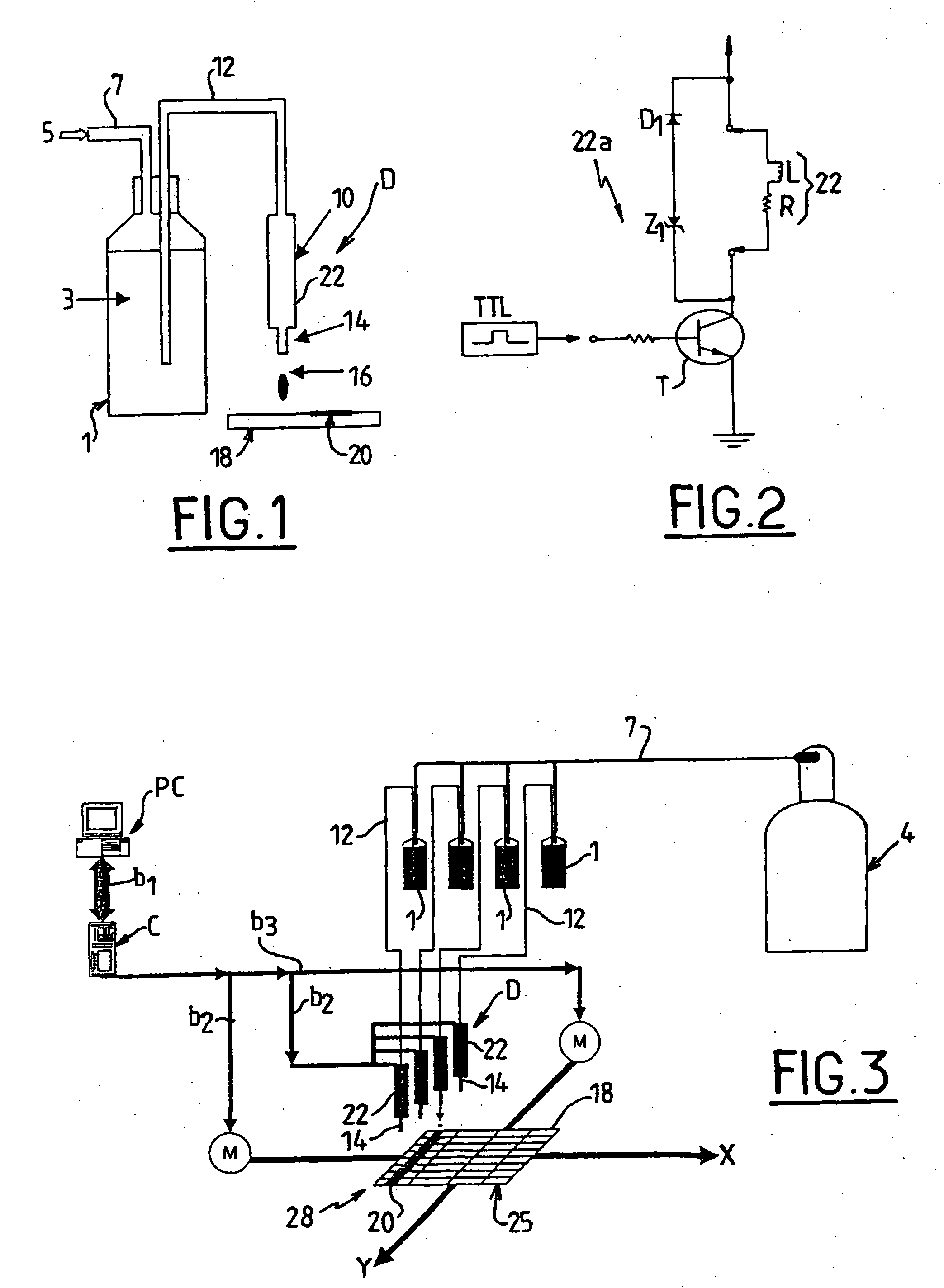
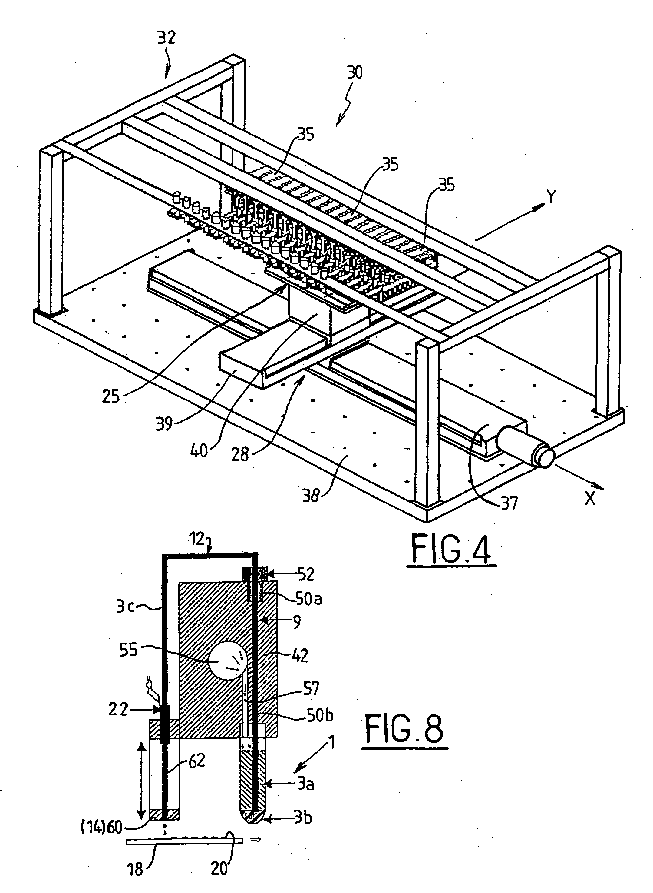
[0076]As shown in FIG. 1, a microprojection device of the invention comprises at least:[0077]a tank 1 storing a reagent 3 in liquid form that is constituted by at least one probe diluted in a suitable solvent;[0078]a source 5 of gas under pressure which is connected to the tank 1 via an inlet tube 7, the gas used being an inert gas such as helium, for example;[0079]an actuator 10 which is connected to the tank 1 by an outlet tube 12 which dips into the reagent 3; and[0080]an ejection nozzle 14 which is mounted at the outlet of the actuator 10.

[0081]In general, the function of the actuator 10 is to cause a microvolume of reagent 3 to be projected through the nozzle 14. The actuator 10 may occupy at least two states, respectively an open state and a closed state. By occupying the open state for a determined length of time, the actuator 10 allows reagent 3 to pass into the nozzle 14 under drive from the pressure of the gas that exists in the tank 1, and providing the pressure is suffic...


PUM

PropertyMeasurementUnit
diameteraaaaaaaaaa
diameteraaaaaaaaaa
diameteraaaaaaaaaa

Abstract

A method of ex situ fabrication of at least one biochip, the method being of the type consisting in projecting onto a substrate a microvolume of reagent comprising at least one probe diluted in a suitable solvent so as to form, after the solvent has been eliminated, a spot comprising said probe, the method consisting in using a microprojection device comprising at least one tank in which the reagent is stored, and at least one source of gas under pressure put into communication with the tank, and in projecting the microvolume of reagent through an ejection nozzle under drive from the pressure exerted by the gas on the reagent.

Description

[0001]The invention relates to method and a machine for ex situ fabrication of low and medium integration biochip arrays.BACKGROUND OF THE INVENTION[0002]In the field of biotechnologies, biochips, and in particular DNA chips, are presented as being completely innovative tools capable of revolutionizing experimental approaches to molecular biology. The advantage of a biochip lies in its ability to identify target biomolecules in parallel with several tens to several millions of probes of different compositions on the same solid structure (glass, silicon, polymer, etc.), the probes being secured by implementing an affinity recognition process between the probes and the chip.[0003]By way of example, a DNA chip is a device designed to enable monocatenary DNA strands to be identified by using the hybridizing process implemented between the strand(s) of the target DNA to be recognized and one of the known-sequence oligonucleotides probes fixed in a defined zone on a solid support, and the...

Claims


Application Information

Patent Timeline
Patent Type & Authority Applications(United States)
IPC IPC(8): C40B50/14C40B60/14G01N35/02B01J4/02B01J19/00C12M1/00C40B40/06G01N35/04G01N35/10G01N37/00
CPCB01J19/0046C40B60/14B01J2219/00378B01J2219/00412B01J2219/00418B01J2219/00527B01J2219/00529B01J2219/00585B01J2219/00596B01J2219/00605B01J2219/00608B01J2219/0061B01J2219/00612B01J2219/00626B01J2219/0063B01J2219/00637B01J2219/00659B01J2219/00677B01J2219/00689B01J2219/00693B01J2219/00702B01J2219/00722B82Y30/00C40B40/06B01J2219/00369
Inventor CABRERA, MICHELJABER, MEHDICLOAREC, JEAN-PIERREBROUTIN, JEROMESOUTEYRAND, ELIANEMARTIN, JEAN-RENE
Owner ECOLE CENT DE LYON
Learn More