Bone fixation plate

a bone screw and fixation plate technology, applied in the field of orthopedic surgery, can solve the problems of instability of bone or joint, increased pain and danger, and instability of bone screws and bones, and achieve the effect of reducing the possibility of traumatizing adjacent soft tissue during use and low cross section profil

Active Publication Date: 2009-07-02
ATLAS SPINE
View PDF41 Cites 68 Cited by
  • Summary
  • Abstract
  • Description
  • Claims
  • Application Information

AI Technical Summary

Benefits of technology

[0013]It is an objective of this invention to provide a bone plate, suitable for anterior lumbar fixation, having countersunk screw holes, a low profile in cross section allowing the bone plate to be countersunk into the bone and a smooth distal surface to reduce the possibility of traumatizing adjacent soft tissue during use.
[0016]Yet another objective of the invention is to provide a bone plate with a locking cap which extends over the area of the countersunk screw holes. The locking cap fits into a large countersunk area of the bone plate covering the countersunk screw holes allowing easy and positive assembly and preventing relative lateral movement between the locking cap and the plate. The locking cap has an aperture and the plate has a receptacle which align when the cap is placed in the countersunk area. A cap screw is threaded into the aligned aperture and receptacle to connect the plate and the cap.

Problems solved by technology

The interface between the bone screws and the bone presents problems of stability and long term usage that have been addressed in different ways.
Severe back-out results in the bone screw working itself out of the bone and / or plate resulting in instability of the bone or joint.
This situation results in increasing pain and danger from the instability, as well as, the movement of the screw.
There may be several reasons for the back-out but anatomical stresses from body movements contribute greatly to the problem.
Such devices are not particularly suited for deployment on the anterior aspect of the spine because of the close proximity of vital soft tissue organs which dictate a smooth, low profile, contoured surface.

Method used


Image

  • Bone fixation plate
  • Bone fixation plate
  • Bone fixation plate

Examples


Embodiment Construction

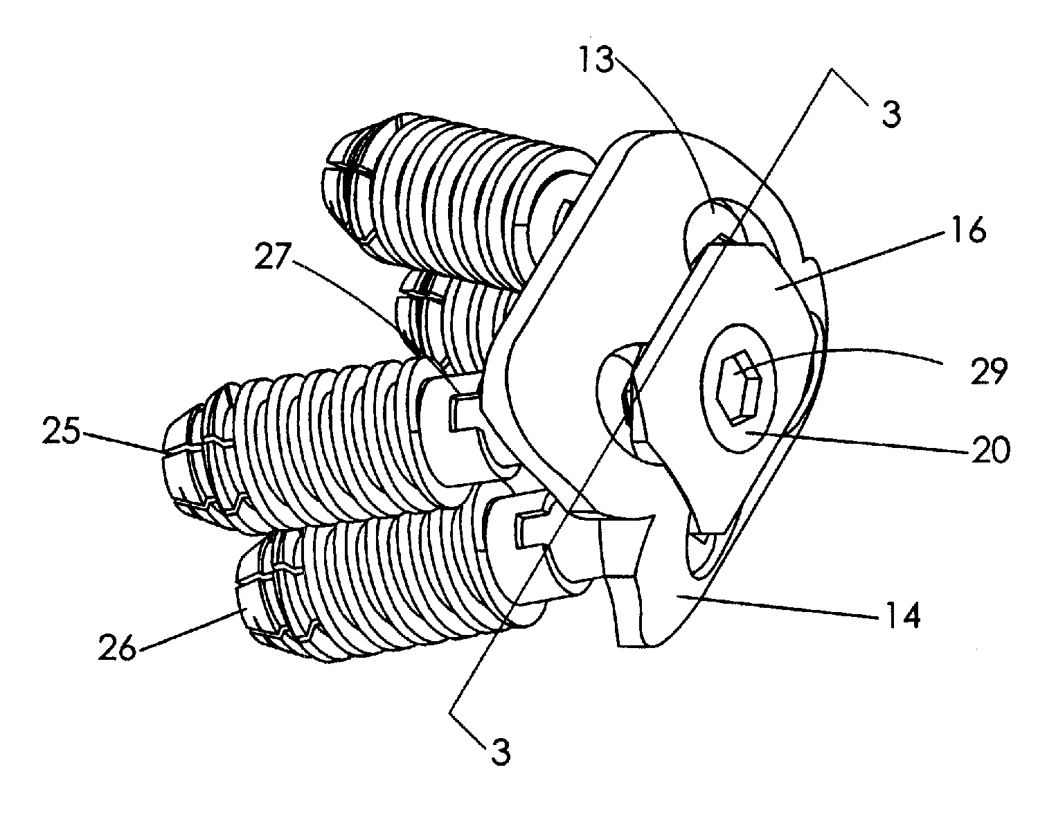
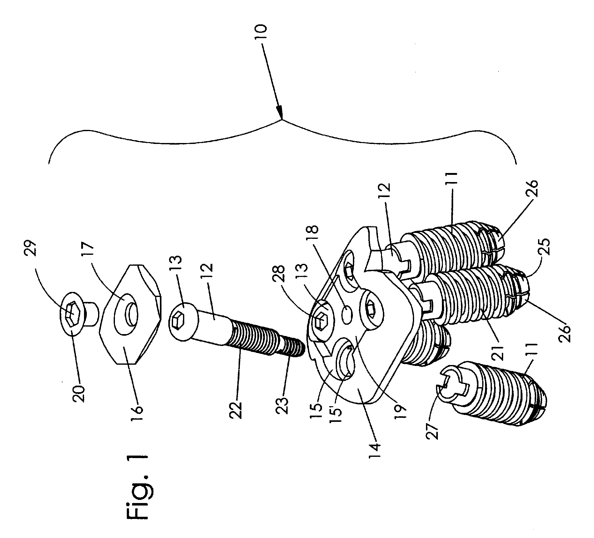
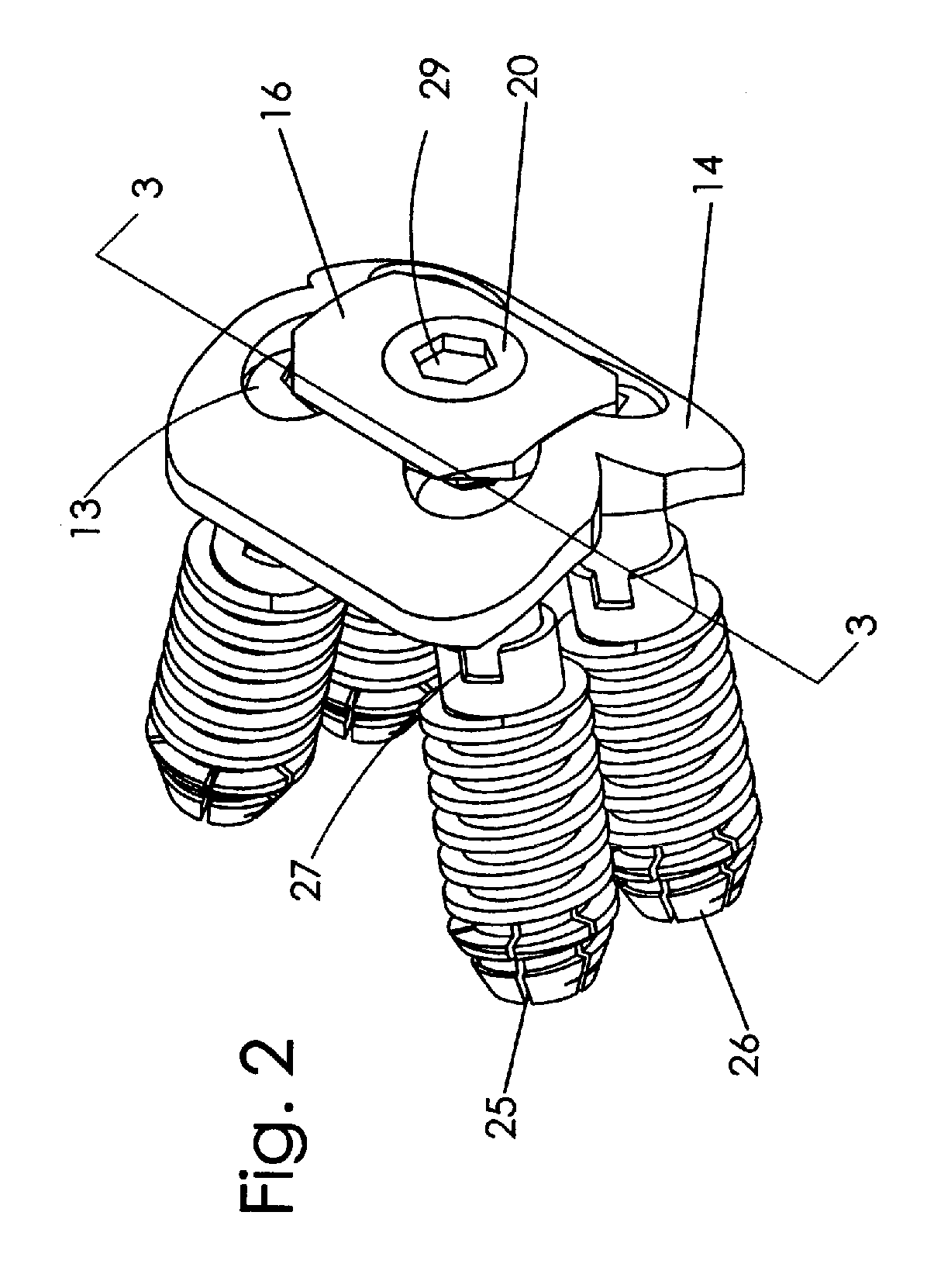
[0037]The bone plate system 10 may be made from any materials having requisite strength and being suitable for use in the body. One complete bone plate system is shown in FIG. 1, FIG. 2 and FIG. 2A though it is understood that several different sizes of interchangeable components may be supplied together as a kit for mixing and matching components to size a system for a particular patient. A kit may have several different sized bone anchors 11 varying in diameter and length with complementary locking screws 12. The different sized locking screws may have the same sized heads 13 to be used in different sized bone plates 14 with screw holes 15′ and countersunk depressions 15 of the same size. There may be several different sized locking caps 16, as shown in FIGS. 2 and 2A, to fit into the different complementary sized countersunk areas 19 of the plates while the aperture 17 and the threaded receptacle 18 are of the same size. The locking cap 16 is connected to the plate 14 by a cap sc...


PUM


Abstract

A bone plate for use in anterior lumbar spinal fixation has interlocking components to prevent dislodgement of the plate due to anatomical forces. The exposed surface of the plate is smooth to prevent trauma to internal body tissue. The plate spans the intervertebral space with each end attached to an adjacent vertebrae by locking screws threadably engaged with tubular bone anchors. The bone anchors include helical members are threaded through the bone plate and inserted into holes within the bone. The plate has a countersunk cavity including portions overlapping the locking screws. A locking cap fits in the cavity to secure the other end of the locking screws from backing-out of the plate. The locking cap includes at least two chamfered portions that cooperate with mating recesses in the countersunk cavity of the bone plate.

Description

CROSS REFERENCE TO RELATED APPLICATIONS[0001]This application is a continuation-in-part of application Ser. No. 10 / 419,686, entitled “BONE FIXATION PLATE”, filed Apr. 21, 2003, the entire contents of which is hereby expressly incorporated by reference.FIELD OF THE INVENTION[0002]This invention relates to the field of orthopedic surgery and, more particularly, to spinal fixation.BACKGROUND OF THE INVENTION[0003]The use of bone pins and plates for reducing fractures is well known in orthopedic medicine. The pins and plates extend across discontinuities in a bone to fix the broken ends in relation to each other to reduce pain and promote rapid healing without deformity. These devices are secured to the bone by bone screws or nails driven into the bone. More recently, pins, rods, plates and cages have been used to stabilize bone and joints that have deteriorated naturally or as a result of prior trauma. The bone plate of this invention is useful in all these situations.[0004]The interfa...

Claims


Application Information

Patent Timeline
Patent Type & Authority Applications(United States)
IPC IPC(8): A61B17/70A61B17/58
CPCA61B17/686A61B17/7059A61B17/8635A61B17/8042A61B17/863A61B17/8038
Inventor BAYNHAM, MATTHEW G.BAYNHAM, G. CLAY
Owner ATLAS SPINE
Why Eureka
Try Eureka