Machine diagnosing method and device therefor

a machine and diagnostic method technology, applied in the field of machine diagnostic methods and devices therefor, can solve the problems of low diagnostic reliability, inability to diagnose abnormalities, and hardly specified abnormal parts, so as to improve diagnostic reliability and facilitate the treatment of parts such as maintenance or the lik

Inactive Publication Date: 2009-07-02
OKUMA CORP
View PDF2 Cites 19 Cited by
  • Summary
  • Abstract
  • Description
  • Claims
  • Application Information

AI Technical Summary

Benefits of technology

[0023]According to the invention of the sixth aspect, a following effect can be acquired in addition to the effects of the inventions of the fourth or fifth aspects. That is, a machine damage coefficient can be calculated more precisely based on a plurality of drive object driving forces and positional deviations.
[0024]According to the invention of the seventh aspect, a following effect can be acquired in addition to the effect of any one of the inventions of the fourth to sixth aspects. That is, since a second damage coefficient is applied, the abnormality of the guide unit can be diagnosed, and thus the reliability of a machine diagnosis can be improved.
[0025]According to the invention of the eighth aspect, the following effect can be acquired in addition to the effect of the invention of the seventh aspect. That is, a sign of abnormality can be spotted by an increase of the probability, and thus a diagnosis can be performed before a serious trouble occurs.
[0026]According to the invention of the ninth aspect, the following effect can be acquired in addition to the effect of any one of the inventions of the fourth to eighth aspects. That is, an abnormal part can be specified with the diagnosis, and thus treatment of the part such as maintenance or the like can be performed easily.

Problems solved by technology

However, in the abnormality detection in Patent document 2, the existence of abnormality in a feed spindle is determined by only a value of a motor torque, and thus reliability of diagnosing is not high.
Further, when an external force such as a machining force is inputted, abnormality cannot be diagnosed, and an abnormal part is hardly specified.

Method used


Image

  • Machine diagnosing method and device therefor
  • Machine diagnosing method and device therefor
  • Machine diagnosing method and device therefor

Examples


embodiment 1

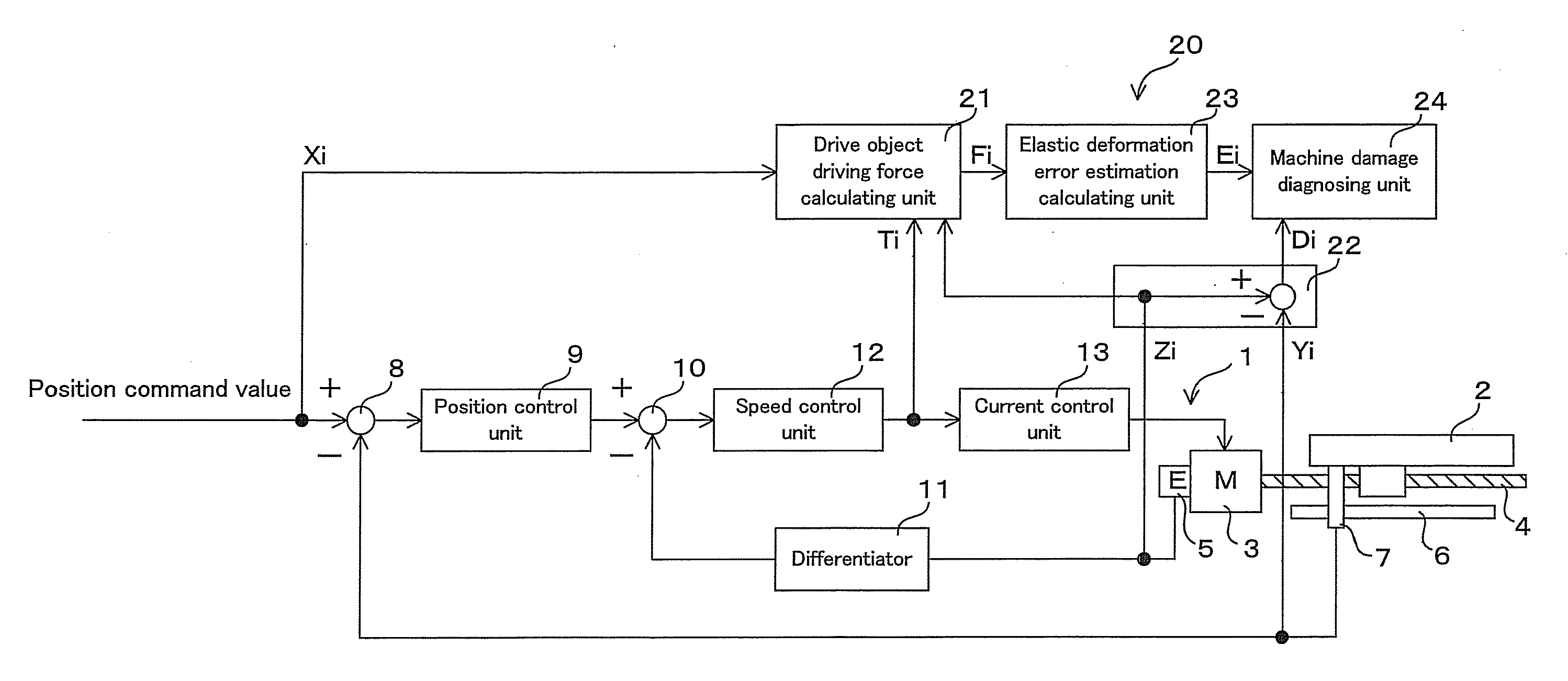
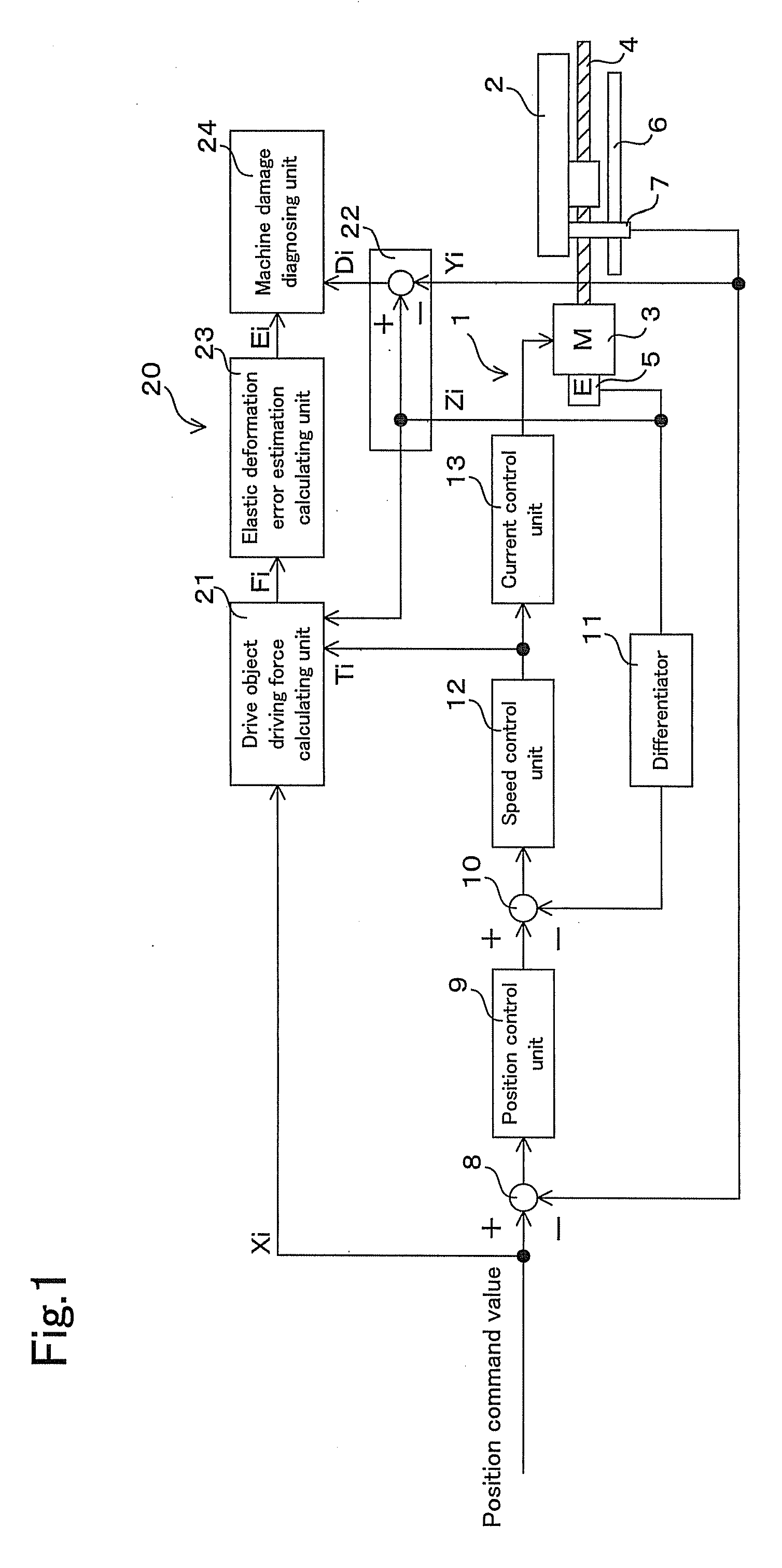
[0036]FIG. 1 is a constitutional block diagram illustrating one example of a machine diagnosing device used for a machine tool, and the device is provided in a position control device of a table. First of all, a position control device 1 of a machine tool has a table 2 as a drive object which is slidably provided with a ball screw 4 rotated by driving a servo motor 3. The servo motor 3 has a first position detector 5 for detecting a rotation position of the table 2. The table 2 has a second position detector 7 which is slidably attached along a scale 6 parallel to the ball screw 4 and can detect the sliding position of the table 2.

[0037]Further, a position command value is inputted from a NC device (not illustrated) to the position control device 1, and a subtractor 8 subtracts the position detected value (a sliding position signal of the table 2) acquired by the second position detector 7 using the position command value, and calculates a positional deviation. A position control un...

embodiment 2

[0054]Then, another embodiment of the present invention will be described. It should be noted that same constitutional parts as those in the embodiment 1, such as a position control device of a table, are used with the same reference numerals and the descriptions of the same constitutional parts are omitted.

[0055]In a machine diagnosing device 20a illustrated in FIG. 3, a drive object driving force Fi acquired by a drive object driving force calculating unit 21 and a positional deviation Di acquired by a positional deviation calculating unit 22 are inputted into a machine information storing unit 25 with a position command value Xi. The machine information storing unit 25 performs machine information storing processing described below and stores each value. Then, a damage coefficient calculating unit 26 calculates a machine damage coefficient ζ by a routine described below based on the stored drive object driving force Fi, positional deviation Di, and a position command value Xi. A ...

embodiment 3

[0064]As compared with the embodiment 2 illustrated in FIG. 3, a machine diagnosing device 20b illustrated in FIG. 5 is different in a point that a main spindle motor torque Tsi is inputted into a machine information storing unit 25 from a main spindle motor control device 27 of a machine tool. Thus, in machine information storing processing by the machine information storing unit 25, as shown in FIG. 6, the machine information storing unit 25 further determines whether an absolute value |Tsi| of a mains spindle motor torque is smaller than Tsmin in S18, where Tsmin is a minimum value of the main spindle motor torque previously set as an initial-setting value. When the absolute value |Tsi| is greater than Tsmin, the machine information storing unit 25 does not perform the storing processing. Only when the absolute value |Tsi| is smaller than Tsmin, the machine information storing unit 25 stores a drive object driving force Fi, a position command value Xi, a positional deviation Di, ...


PUM


Abstract

A machine diagnosing device 20 includes a drive object driving force estimating unit 21 for estimating drive object driving force based on a torque command value toward a servo motor 3 which is acquired using a position command value, an elastic deformation error estimating unit 23 for estimating an elastic deformation error of a ball screw 4 with the drive object driving force, and a positional deviation calculating unit 22 for calculating a positional deviation using a rotation position of the servo motor 3 and the position of a table 2, and a machine damage diagnosing unit 24 for diagnosing a machine damage by calculating a machine damage coefficient using the elastic deformation error and the positional deviation, comparing the obtained machine damage coefficient with a previously set threshold value, and diagnosing a damage state of the drive object.

Description

[0001]This application claims the benefit of Japanese Patent Application Number 2007-337601 filed on Dec. 27, 2007, the entirety of which is incorporated by reference.BACKGROUND OF THE INVENTION[0002]1. Field of the Invention[0003]The present invention relates to a machine diagnosing method for diagnosing a damage state such as an abrasion of a part or an increase of operation resistance in a machine tool and an industrial machine, and also relates to a device therefor.[0004]2. Description of the Background Art[0005]For example, in a machine tool, a full closed loop position control device is used for positioning a table or the like to be driven with high accuracy. As described in Patent document 1, the full closed loop position control device includes a first position detector for detecting a rotation position of a motor and a second position detector for directly detecting a position of a drive object driven by the motor. The full closed loop position control device controls a pos...

Claims


Application Information

Patent Timeline
Patent Type & Authority Applications(United States)
IPC IPC(8): G06F17/00B23Q15/00G01M99/00G05B19/18G05D3/12H02P29/00
CPCG05B19/4065
Inventor NORIHISA, TAKASHI
Owner OKUMA CORP
Why Eureka
Try Eureka