Manufacture of Multi-Leaf Collimators

a collimator and multi-leaf technology, applied in the direction of electrical equipment, electrical machining apparatus, cells, etc., can solve problems such as interference with the conduction process

Inactive Publication Date: 2009-07-09
ELEKTA AB
View PDF13 Cites 3 Cited by
  • Summary
  • Abstract
  • Description
  • Claims
  • Application Information

AI Technical Summary

Benefits of technology

[0011]The current that is passed can, if desired, be controlled to a profile that will affect the manner of erosion. Thus, the current profile can be a steady on / off current, or it can be pulsed. One known arrangement is for the current to rise to a peak, then fall to zero, followed by a brief reverse flow. The brief reverse flow acts to clean the mould of any material that may have been plated onto it and thus preserves the life thereof.

Problems solved by technology

Such surface coatings may interfere with the conduction process.

Method used


Image

  • Manufacture of Multi-Leaf Collimators
  • Manufacture of Multi-Leaf Collimators

Examples


Embodiment Construction

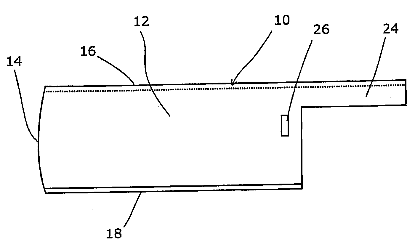
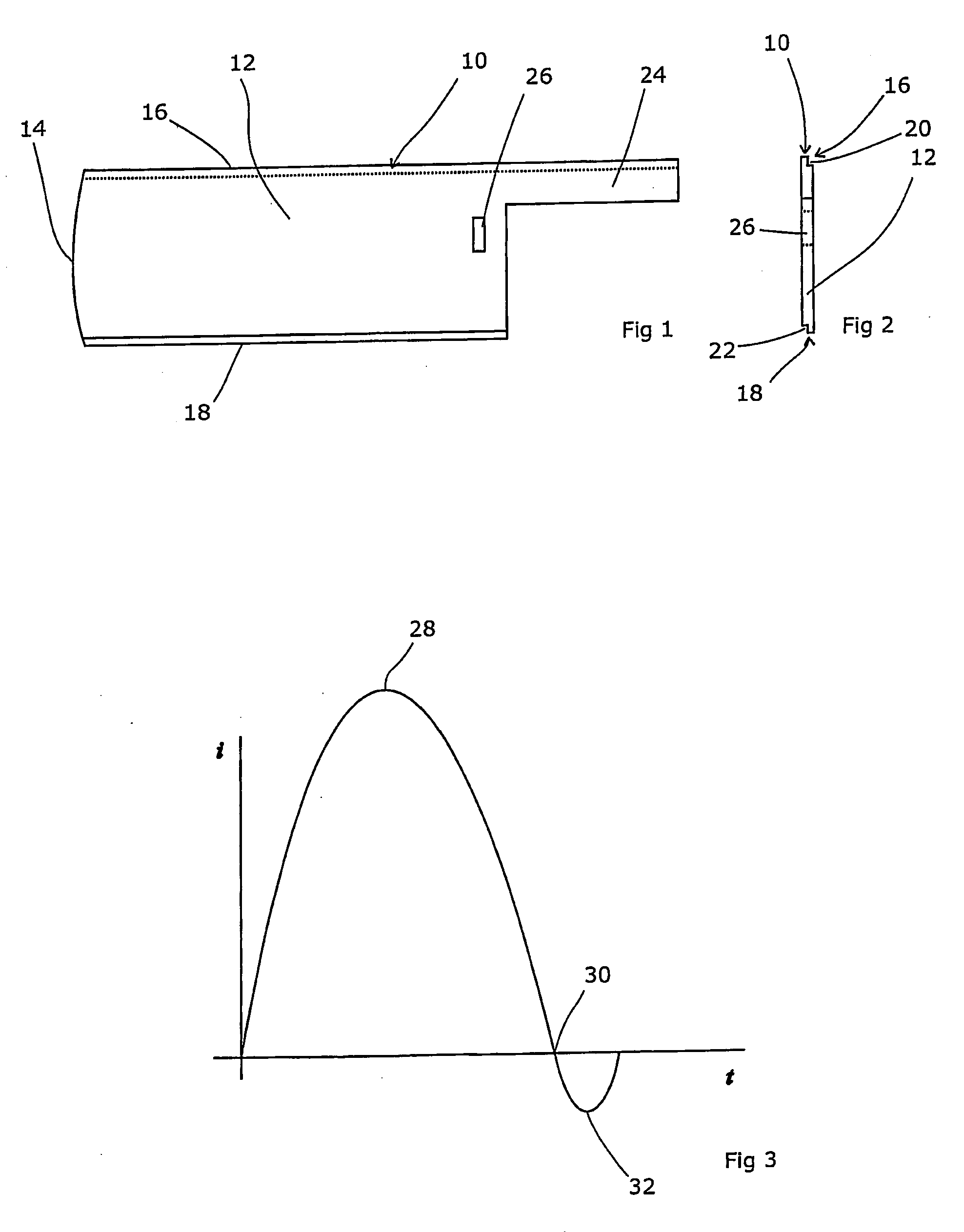
[0015]As mentioned above, leaves for multi-leaf collimators have to date been manufactured by spark erosion. Other known techniques have proved to be less suitable due to the properties of the tungsten material from which the leaves need to be made and the relatively complex shape that is required, as shown in FIGS. 1 and 2.

[0016]Referring to these figures, the leaf 10 consists generally of a body section 12 whose purpose is to block the x-ray beam into which it is caused to protrude. This needs to be relatively deep in order to cast a sufficiently black shadow. Its width is of course dictated by the resolution of the multi-leaf collimator of which it will form part, and is therefore relatively narrow.

[0017]The forward tip 14 of the leaf is rounded so as to present a smooth edge with minimum penumbra regardless of the distance by which the leaf projects into the beam. Given that the x-rays emanate from what can be considered to be a fixed point source, as the leaf is moved further i...


PUM

PropertyMeasurementUnit
conductiveaaaaaaaaaa
constant currentaaaaaaaaaa
currentaaaaaaaaaa

Abstract

We propose to shape the leaf by the use of electro-chemical machining (ECM). ECM is a technique by which a blank is suspended within a mould, with a small gap therebetween. A conductive fluid is caused to flow through the gap, and a large electrical current is passed from the mould to the blank. The blank steadily erodes, dissolving into the fluid. The fluid should not provoke a reaction from the material of the blank, such as a surface oxide. Sodium Chloride solution is a common choice. The current that is passed can, if desired, be controlled to a profile that will affect the manner of erosion. Thus, the current profile can be a steady on/off current, or it can be pulsed. One known arrangement is for the current to rise to a peak, then fall to zero, followed by a brief reverse flow.

Description

FIELD OF THE INVENTION[0001]The present invention relates to the manufacture of multi-leaf collimators.BACKGROUND ART[0002]Multi-leaf collimators (MLCs) are used (principally) in the field of radiotherapy. A beam of radiation is directed toward a patient and must be collimated to fit the shape of the area to be treated. It is important to ensure that the dose in the areas outside that shape is as low as possible, but also that the whole area is treated. If areas are left untreated then the likelihood of recurrence is increased, whereas if non-treatment regions are irradiated then damage will be caused to healthy tissue resulting in greater side effects and longer recovery times after treatment.[0003]As the treatment area is rarely rectilinear, multi-leaf collimators are employed. These comprise an array of finger-shaped tungsten leaves, each disposed in a parallel relationship and each able to move longitudinally relative to the others. By moving each leaf to a selected position, a ...

Claims


Application Information

Patent Timeline
Patent Type & Authority Applications(United States)
IPC IPC(8): B23H3/00G21K1/02
CPCG21K1/02
Inventor BOURNE, DUNCAN NEIL
Owner ELEKTA AB
Why Eureka
Try Eureka