Modular turbine generator and method of operation

a generator and module technology, applied in the field of electric power generation, can solve the problems of increasing the number of existing plants and transmission lines, and the economic and environmental unfavorable development of nuclear power plants, and achieve the effect of reducing and increasing the number of nuclear power plants

Inactive Publication Date: 2008-05-27
CALIFORNIA POWER PARTNERS
View PDF11 Cites 4 Cited by
  • Summary
  • Abstract
  • Description
  • Claims
  • Application Information

AI Technical Summary

Benefits of technology

[0009]A turbo generator according to the present invention includes a turbine engine with compressor, combustor, and turbine; and a generator drivingly linked to the compressor and turbine. A microprocessor-based inverter having multiple modes of operation is electrically connected to the generator. In order to start the turbine, the inverter connects to and supplies fixed current, variable voltage, variable frequency, AC power to the permanent magnet motor / motor, thus driving the permanent magnet motor / motor as a motor to accelerate the gas turbine. During this acceleration, and at the appropriate time, an ignition source (i.e., such as a spark) is provided along with fuel introduced in the correct volume and sequence, and self-sustaining gas turbine operating conditions are reached.
[0012]In order to preserve the power output level of the turbo generator during conditions of high ambient temperature, a dual function evaporative cooler is associated with the turbo generator. This dual function evaporative cooler cools both the intake air to the turbine engine, as well as cooling air utilized for cooling the electronic control and power conditioning circuitry. Accordingly, the turbine engine has both improved power output and efficiency during high ambient temperature conditions compared to the performance this engine would provide were the evaporative cooler not employed. Further, the electronic circuitry of the power conditioning and control section of the turbo generator is prevented from exposure to excessively high temperature conditions, and the life of the electronic components is thus preserved.

Problems solved by technology

While plans for huge power plants are being shelved because of high costs and environmental concerns, new customers must still be supplied with electrical power.
Existing plants and transmission lines are simply becoming overwhelmed in some areas.
Nuclear power plants are also fast becoming economically and environmentally undesirable.

Method used


Image

  • Modular turbine generator and method of operation
  • Modular turbine generator and method of operation
  • Modular turbine generator and method of operation

Examples


Embodiment Construction

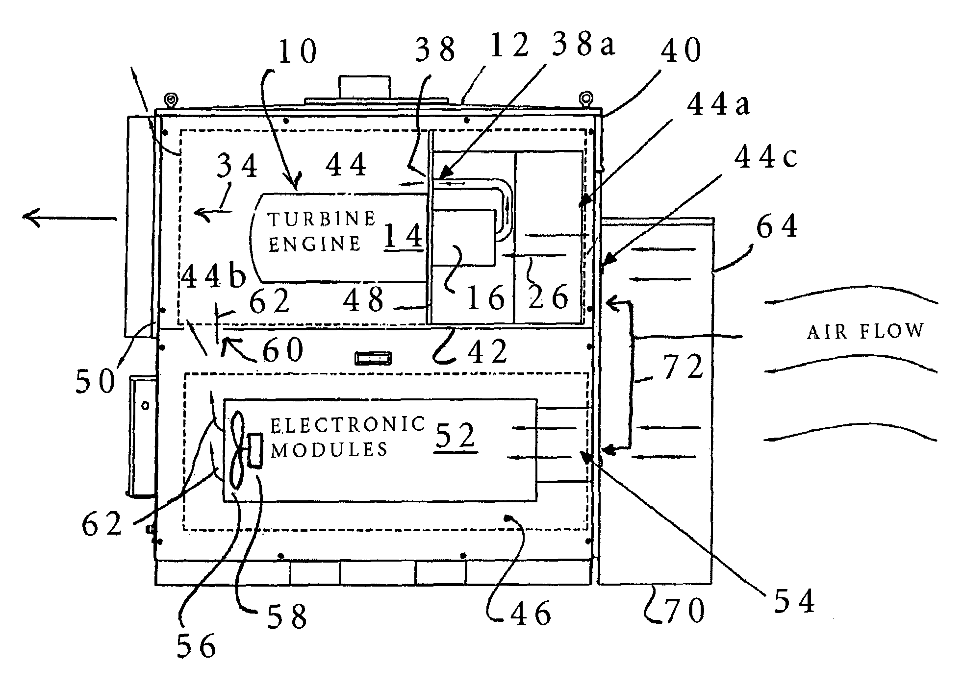
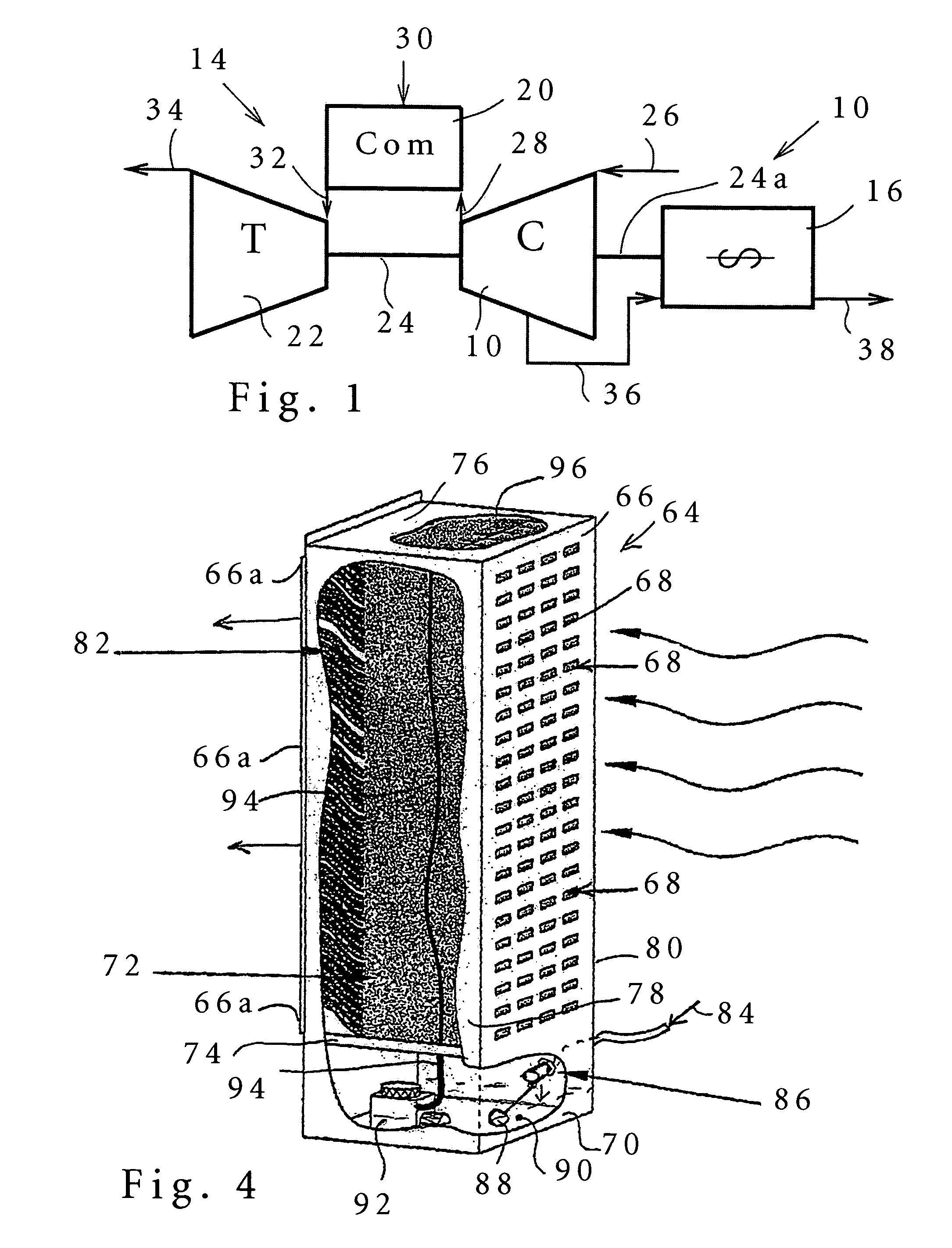
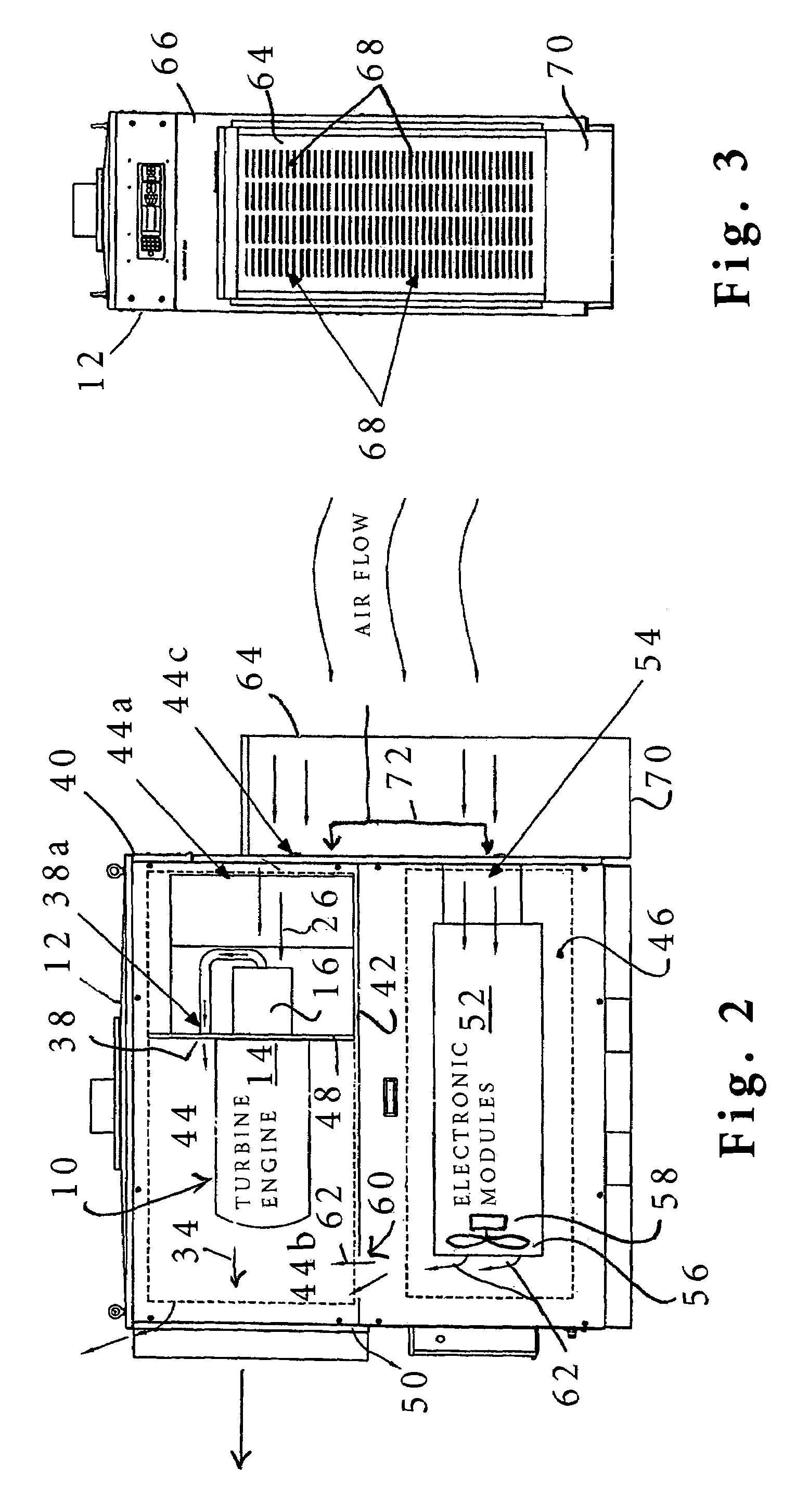
[0021]A turbine engine and generator portion 10 of a modular permanent magnet turbo generator 12 (best seen in FIGS. 2 and 3) is illustrated in FIG. 1. The portion 10 includes a turbine engine 14 (sometimes referred to as a power head), and a permanent magnet generator / motor 16. The turbine engine 14 includes a compressor 18, combustor 20, and turbine 22. The turbine 22 drives a shaft 24 drivingly coupled to the compressor 18, and this driving connection includes a portion 24a drivingly connecting to and providing shaft t power to the generator 16. Compressor 18 receives inlet air (as is indicated by arrow 26 and delivers pressurized combustion air to the combustor 20, as is indicated by arrow 28. The combustor receives the pressurized combustion air 28 along with a supply of fuel, indicated by arrow 30, to maintain combustion providing a flow of pressurized combustion products. These pressurized combustion products flow from the combustor to the turbine 22, as is indicated by arrow...


PUM


Abstract

A modular turbine generator includes both a turbo generator, and electrical power conditioning and control circuitry. During conditions of high ambient temperature the turbo generator may lose both power output and efficiency, while the electrical circuitry suffers from shortened service life or failure because of the high temperatures experienced. In order to preserve power output and efficiency for the turbo generator, as well as extending the service life span for the electrical power conditioning and control circuitry, a dual function evaporative cooler is provided. This cooler provides evaporatively cooled air both to the turbine engine and to the electrical circuitry by utilizing a single evaporative pad, along with a single water source and recirculation pump, all received in a compact cabinet.

Description

TECHNICAL FIELD[0001]This invention is in the field of electrical power generation, and relates more particularly to an improved modular turbo generator and method of its operation for sustaining electrical output level despite high ambient temperature conditions.RELATED TECHNOLOGY[0002]Electric utilities are now grappling with the challenge of deregulation and competition at a time of relatively slow growth in electricity demands. While plans for huge power plants are being shelved because of high costs and environmental concerns, new customers must still be supplied with electrical power. Existing plants and transmission lines are simply becoming overwhelmed in some areas. Nuclear power plants are also fast becoming economically and environmentally undesirable.[0003]One alternative to generating electrical power on a more local basis, minimizing reliance on long distance power transmission, is called a “turbo generator.” Such a turbo generator is a modular unit, and this turbo gen...

Claims


Application Information

Patent Timeline
Patent Type & Authority Patents(United States)
IPC IPC(8): F02C3/30
CPCF02C7/12F05D2260/205
Inventor SCALONE, JOHN
Owner CALIFORNIA POWER PARTNERS
Why Eureka
Try Eureka