
System and method for logo identification and verification

Active Publication Date: 2009-07-09
NOVANTA CORP
View PDF15 Cites 25 Cited by
  • Summary
  • Abstract
  • Description
  • Claims
  • Application Information

AI Technical Summary

Benefits of technology

[0006]It is therefore a principal object and advantage of the present invention to provide a system and method for ensuring the authenticity of medical devices.
[0007]It is an additional object and advantage of the present invention to provide a system and method for ensuring the safety of replacement parts.
[0008]It is a further object and advantage of the present invention to provide a system and method for improving the effectiveness of authentication systems.
[0009]It is another object and advantage of the present invention to provide a system and method for to determine the proper positioning of an authenticating indicia.
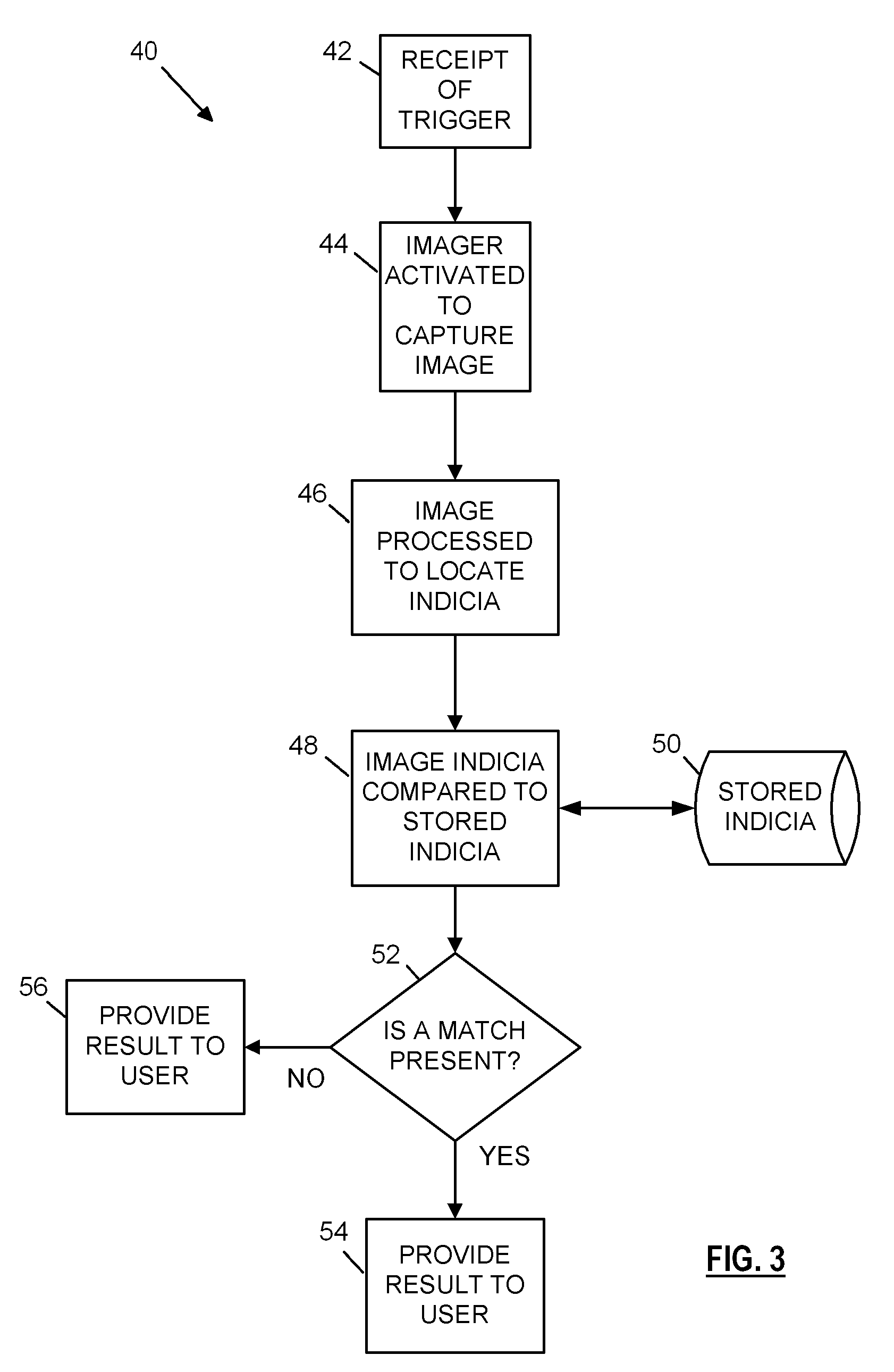
[0010]In accordance with the foregoing objects and advantages, the present invention provides a system for identifying manufacturer specific indicia, such as a logo or trademark, that is applied to a device, such as medical implement, and verifying that the appropriate indicia is present on the device. The system comprises an optical imager for capturing optical images of the target device and a microcontroller interconnected to the imager for processing the optical image to extract image information and verify that the contents of the image reflect the appropriate manufacturer or supplied indicia required by a host device. The microcontroller is programmed to process the image information to determine if the requisite indicia is present and, if so, verify that the indicia is acceptable. The decision may then be provided to a host device, such as a medical device, thereby providing a means by which access to the medical device may be controlled. For example, if the proper indicia are not presented to the imager, a control signal may be passed to the host device indicating that the device should not be enabled for use.

Problems solved by technology

While these systems provide basic identification capabilities, they lack sophisticated processing capabilities, provide only rudimentary information to the host unit, may not be easily upgraded in the field, are not always secure (e.g., wrong instrument for wrong application), cannot distinguish between inferior “knock-off” implements that may be unintentionally or intentionally attached to the base unit, such as an implement made by a competing manufacturer, and do not always effectively distinguish between similar implements.
In addition, the conventional systems lack any ability to determine the location or orientation of a device based on the orientation and position of an indentifying indicia.

Method used


Image

  • System and method for logo identification and verification
  • System and method for logo identification and verification
  • System and method for logo identification and verification

Examples


Embodiment Construction

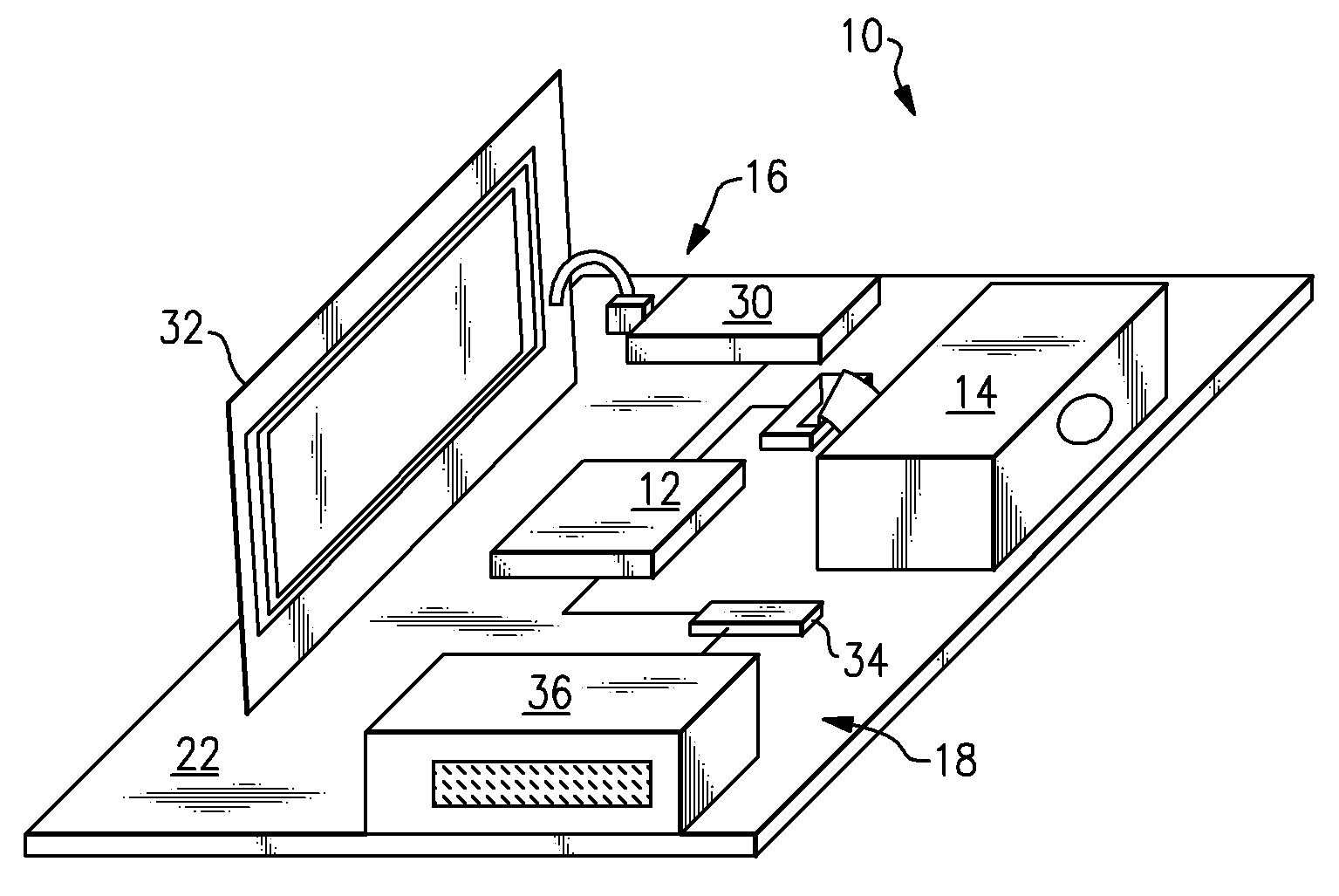
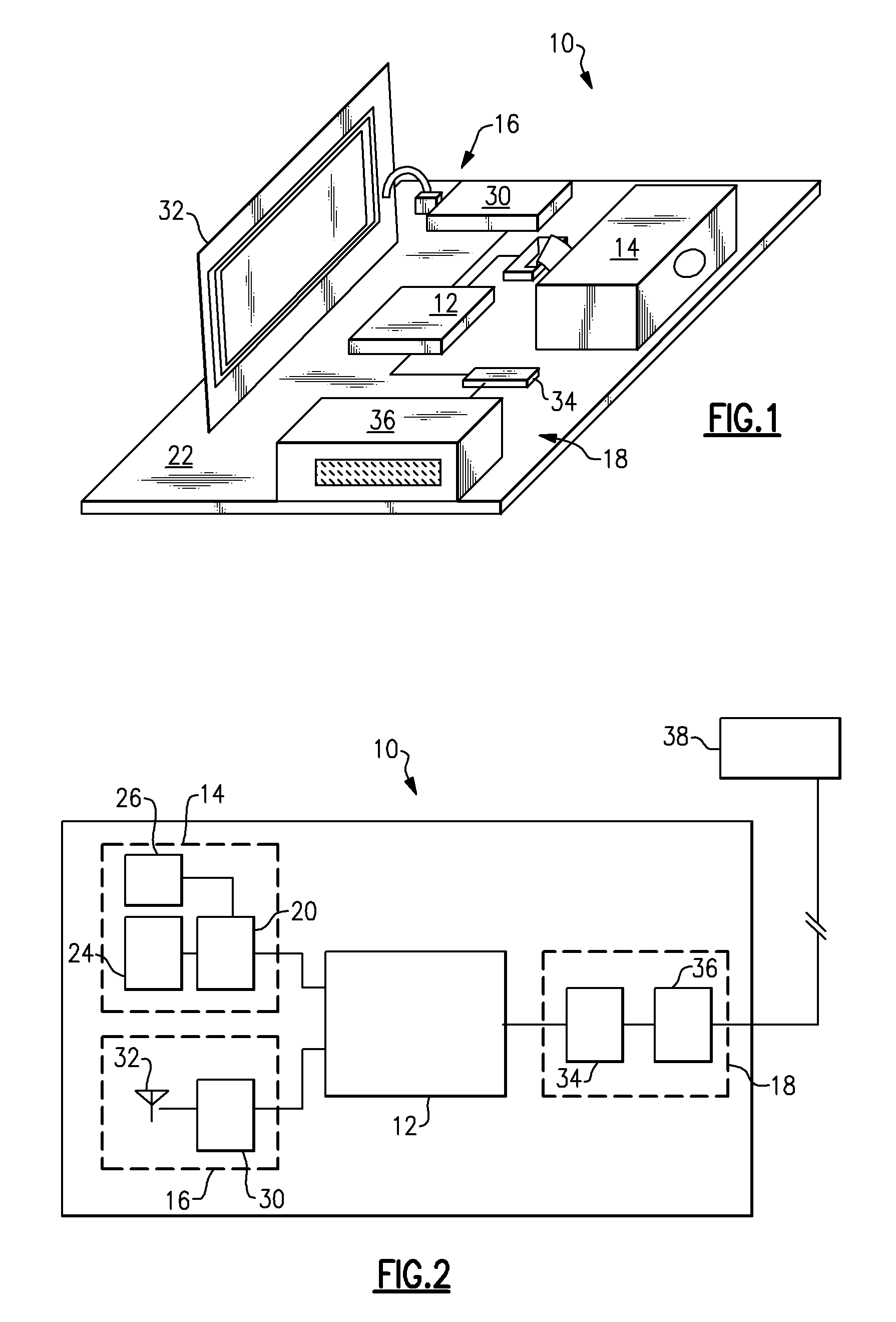
[0015]Referring now to the drawings, wherein like reference numerals refer to like parts throughout, there is seen in FIG. 1 an indicia recognition system 10 according to the present invention. System 10 comprises a microcontroller 12 that is interconnected to a first optical imager 14 and / or an RFID unit 16 to a host interface 18. It should be recognized by those of skill in the art that RFID unit 16 is an optical feature not necessary to the present invention, but which may provide additional benefits and security. System 10 may be arranged on a single printed circuit board 22 and encased as a single unit or housing. Integration of imager 14 and RFID unit 16 through interface 18 allows for combining control of operation of both submodules, such as RFID reading and barcode, through system 10.

[0016]Referring to FIG. 2, optical imager 14 comprises an image engine 20 having image processing circuitry interconnected to microcontroller 12 for omni-directional optical scanning. Image eng...


PUM


Abstract

A system for automatically identifying a logo or trademark applied to a device and verifying that the logo or trademark is acceptably identifies a compatible device. The system uses an optical imager to capture optical images of the target device and a microcontroller interconnected to the imager for processing the optical image to extract image information and verify that the contents of the image reflect the appropriate manufacturer or supplied indicia required by a host device. The decision reached by the microcontroller may be provided externally to a host device, thereby precluding or allowing use of the device, or provided directly to a user via know means, such as a visual display or audible output.

Description

BACKGROUND OF THE INVENTION[0001]1. Field of the Invention[0002]The present invention relates to data collection systems and, more specifically, to a system and method of logo identification for verifying the compatibility for medical and other devices.[0003]2. Description of the Related Art[0004]Many medical instruments, such as electrosurgical scalpels, include one or more reusable or disposable medical implements that must be attached to or used in connection with a base unit. Safe operation of such medical devices requires that the authentic implement is attached or interconnected to the corresponding base unit, and that the base unit is properly configured for the safe operation of the particular instrument. In other systems employing a single unit or piece of equipment, it may be important simply to verify the authenticity of a particular instrument or device without regard to whether the instrument is compatible.[0005]Conventional identification method for such systems compri...

Claims


Application Information

Patent Timeline
IPC IPC(8): G06K7/10
CPCA61B19/44G06K2209/25G06K9/00A61B2019/448A61B90/90A61B90/98G06V2201/09G06V10/22
Inventor PINE, JEFFREY A.CHEN, MO
Owner NOVANTA CORP
Learn More