Method for manufacturing a solar module in orbit

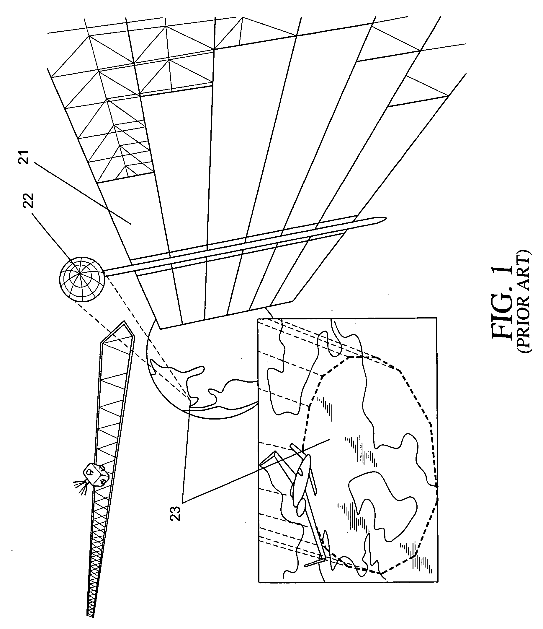
a manufacturing method and solar module technology, applied in the direction of cosmonautic vehicles, transportation and packaging, cosmonautic crew accommodation, etc., can solve the problems of no economic competitiveness, no method proved economically feasible, and cost of launching materials

Inactive Publication Date: 2009-07-09
ROSEMAN PAUL
View PDF33 Cites 20 Cited by
  • Summary
  • Abstract
  • Description
  • Claims
  • Application Information

AI Technical Summary

Benefits of technology

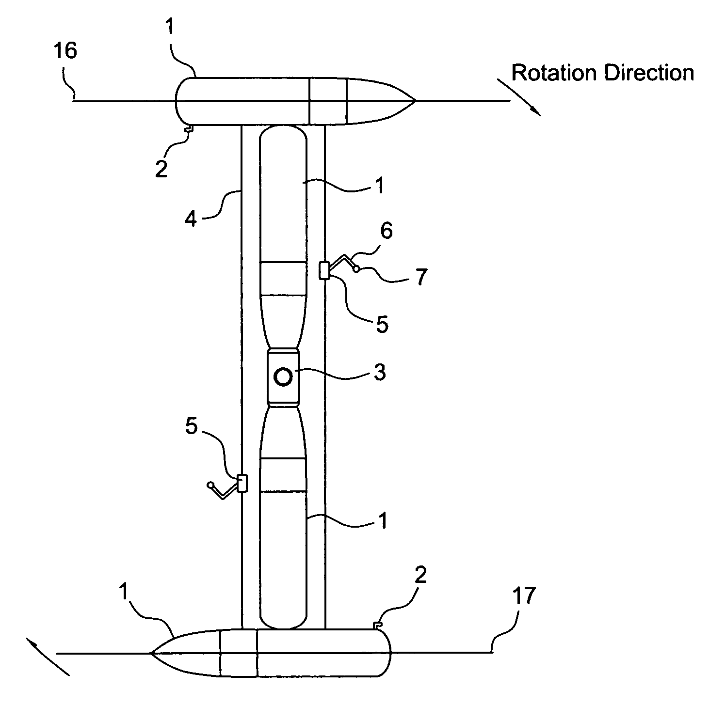
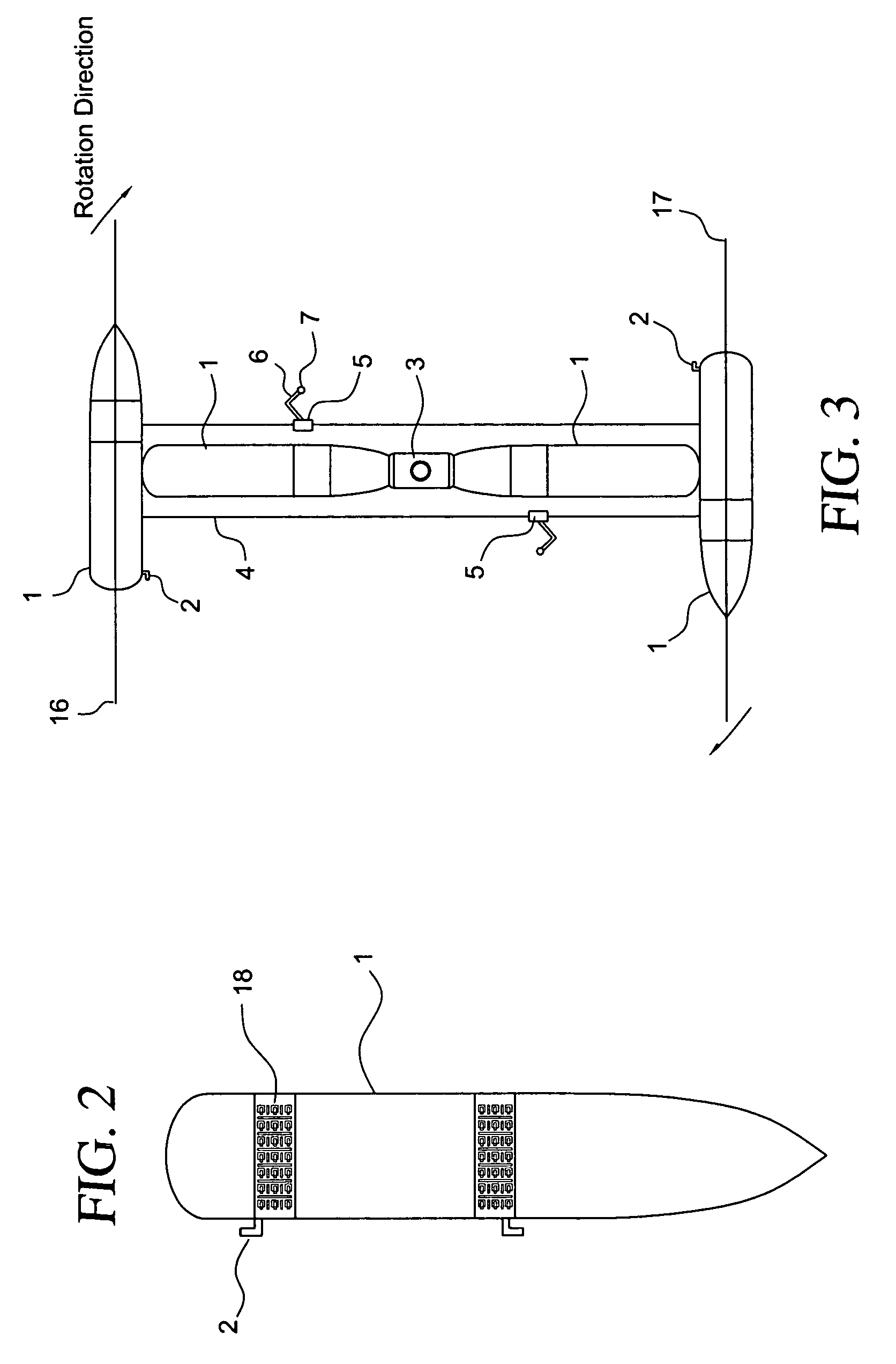
[0015]In accordance with the present invention, the low earth orbit manufacturing facility is created. Empty external tanks from Space Shuttle launches are collected in low earth orbit. They are then joined together, filled with habitat, manufacturing, environment recycling modules and engines. They are then rotated to create an artificial “mars normal” gravity environment.
[0016]Then the facility is used to manufacture the modular components of the Solar Power Satellite System. Additional empty external tanks and expended rocket boosters are collected. They are re-manuf...

Problems solved by technology

This method proved to be too expensive to be feasible.
Because of the high cost of launching materials t...

Method used


Image

  • Method for manufacturing a solar module in orbit
  • Method for manufacturing a solar module in orbit
  • Method for manufacturing a solar module in orbit

Examples


Embodiment Construction

Creation of the Manufacturing Facility:

[0031]In this preferred embodiment for the current space situation, for the creation of the manufacturing facility, an empty external tank (ET) #1 (FIG. 2) from the Space Shuttle is not discarded upon the Shuttle's launch to the International Space Station (ISS). Instead, the empty external tank (ET) is taken into orbit with the Space Shuttle. About 30 miles short of the International Space Station (ISS), the Shuttle disconnects and undocks from the external tank (ET).

[0032]The external tank (ET) is fitted by the Shuttle Manipulator Arm #37 (a standard part of the Space Shuttle) with a station keeping device, which consists of a girdle of solar power cells #18 (FIG. 2) that connects to an ion engine #2 (FIG. 2). The Shuttle crew opens the cargo bay doors #38 (FIG. 12), and take out a wraparound solar panel with an ion engine #18,2 (FIG. 2), using the Shuttle Manipulator Arm #37 (FIG. 12). With the Shuttle Manipulator Arm #37 (FIG. 12), the Shut...


PUM

PropertyMeasurementUnit
Gravityaaaaaaaaaa

Abstract

A geosynchronous Solar Power Satellite System is created by an artificial gravity, closed ecology, multiple use structure in low earth orbit that manufactures modular solar power panels and transmitter arrays. This facility takes empty fuel tanks and expended rocket boosters from launch vehicles that are sent into low earth orbit, and re-manufactures them into structural components. These components are mated to solar cells that are launched from earth. The modular solar panels are transported to geosynchronous orbit by vehicles with ion engines, where the panels are mated to other solar panels to collect power. Structural components are also mated to transmitter elements launched from earth. These are likewise transported to geosynchronous orbit. They are mated to the solar power collecting panels and they beam the collected power back to earth.

Description

RELATED PATENT APPLICATION[0001]This application is related to U.S. Provisional Patent Application No. 60 / 680,861, entitled “SOLAR POWER PLAN”, filed May 13, 2005 in the name of Paul Roseman and incorporated by reference into the subject non-provisional application.FIELD OF THE INVENTION[0002]The present invention relates generally to the creation of a geosynchronous Solar Power Satellite System, and more particularly to the creation of an artificial gravity, closed ecology, multiple use structure in low earth orbit that manufactures modular solar power panels, modular transmitter arrays and truss structures.[0003]In particular, a method of creating a geosynchronous solar power satellite system from a low earth orbit structure with artificial gravity and closed ecology that links re-manufactured expended rocket boosters with solar cells created on earth into modular solar panels. It also links re-manufactured expended rocket boosters with microwave transmitter elements created on ea...

Claims


Application Information

Patent Timeline
IPC IPC(8): B64G1/60B64G1/00B64G1/44H01P11/00
CPCB64G1/12B64G1/14B64G1/222B64G1/402Y10T29/49016B64G1/428B64G1/44B64G1/46B64G1/646B64G1/405
Inventor ROSEMAN, PAUL
Owner ROSEMAN PAUL
Why Eureka
Try Eureka