Motor control device

a technology of motor control and control device, which is applied in the direction of motor/generator/converter stopper, process and machine control, emergency protective circuit arrangement, etc., can solve the problems of unnecessarily increasing the surface area of the substrate, achieve high vibration resistance, suppress warpage, and reliably fix the substrate

Active Publication Date: 2009-07-09
AISIN AW CO LTD
View PDF8 Cites 42 Cited by
  • Summary
  • Abstract
  • Description
  • Claims
  • Application Information

AI Technical Summary

Benefits of technology

[0009]The present invention was conceived in light of the foregoing issue, and it is an object of the present invention to provide a control device for an AC motor that is capable of securing insulation between a low-voltage circuit and a high-voltage circuit, while also achieving a compact size.

Problems solved by technology

JP-A-2006-280148 enlarges an insulation area where components cannot be mounted, and unnecessarily increases the surface area of the substrate.

Method used


Image

  • Motor control device
  • Motor control device
  • Motor control device

Examples


Embodiment Construction

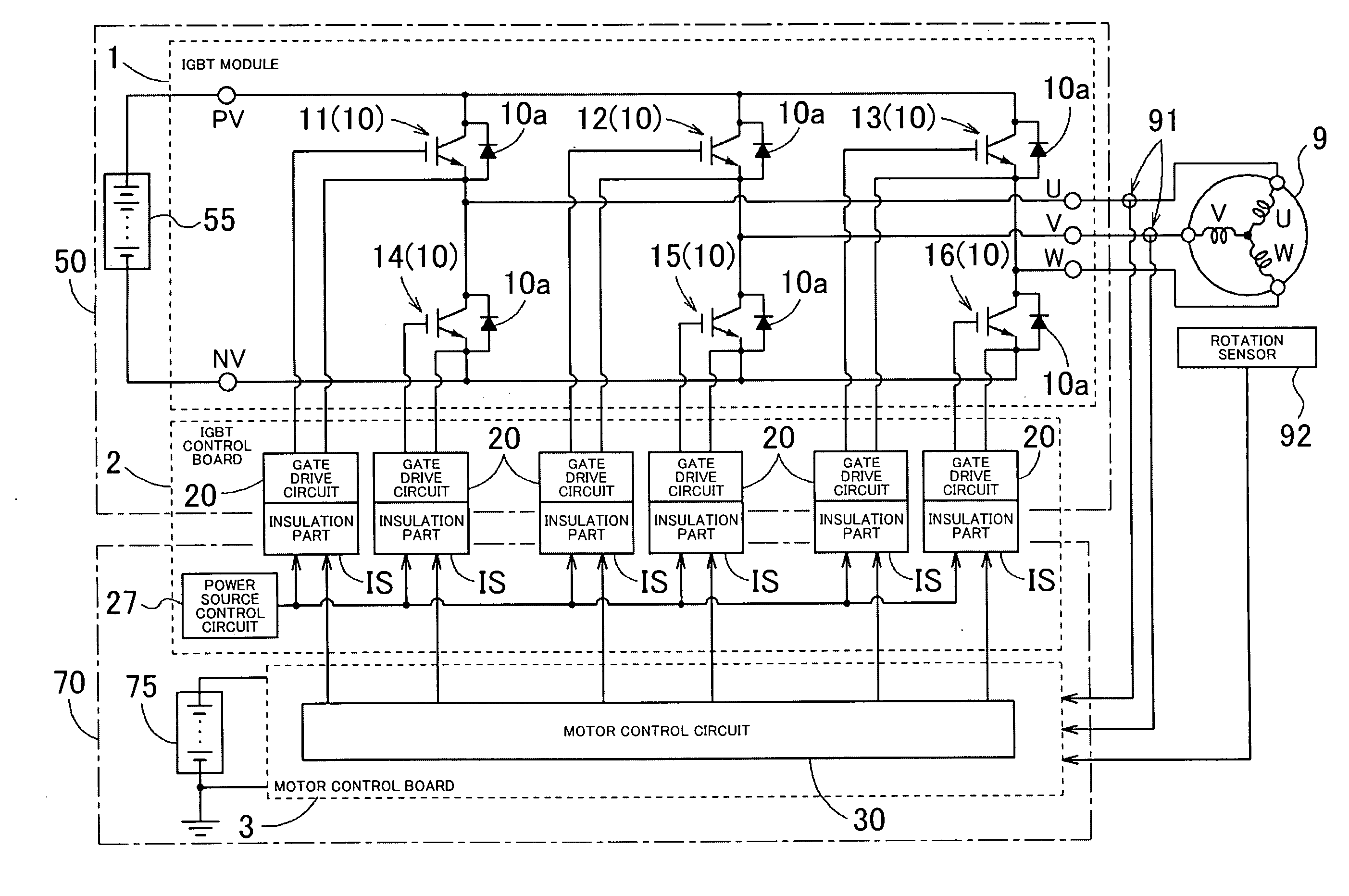
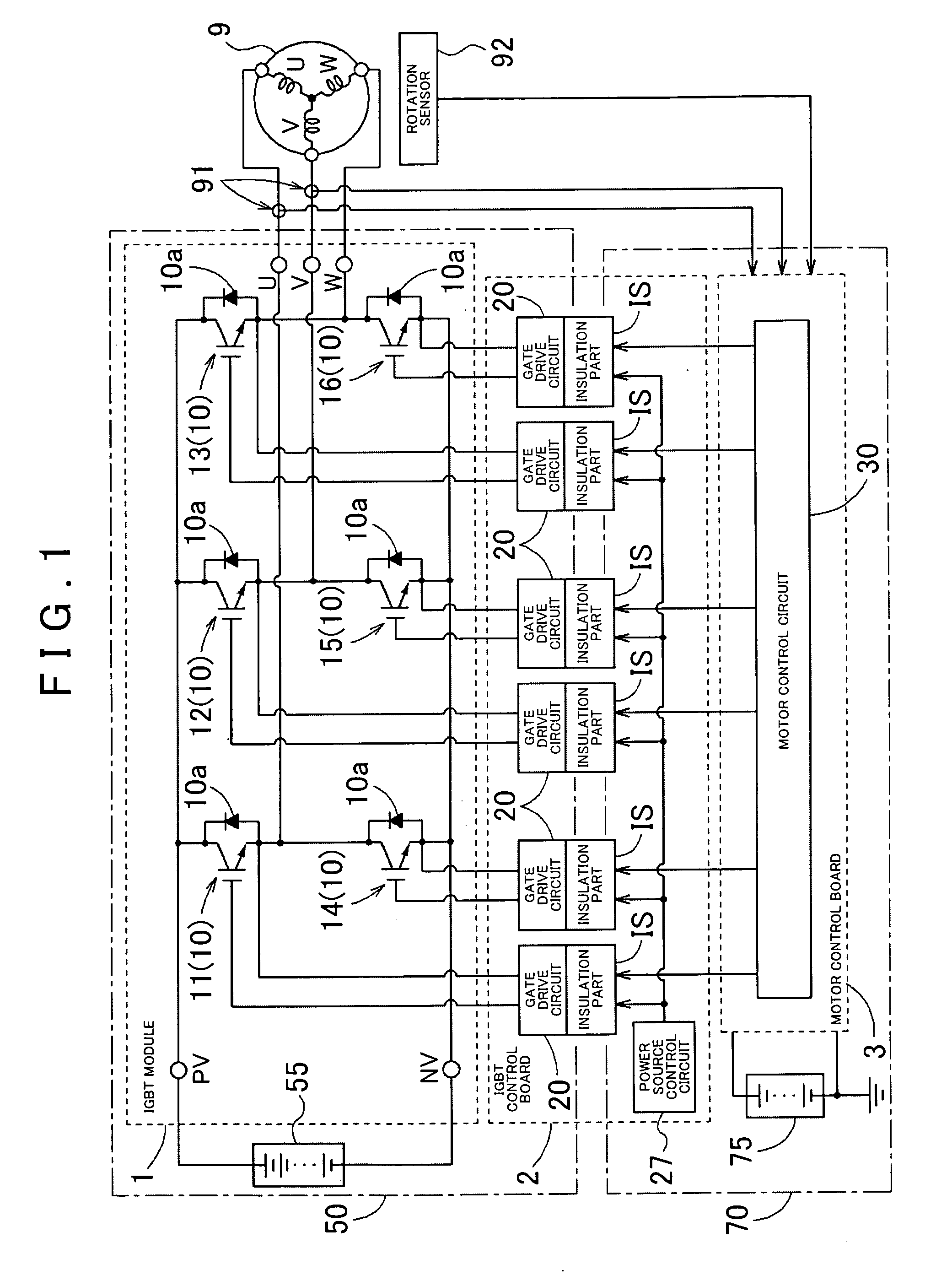
[0041]An embodiment of the present invention as exemplified by a motor control device for controlling a power motor of an electric vehicle or a hybrid vehicle will be described below. Referring to FIGS. 1 to 3, a circuit configuration of the motor control device will be explained first. FIG. 1 is a block diagram schematically showing a circuit configuration of the motor control circuit according to the present invention. As shown in FIG. 1, the motor control device for controlling a three-phase AC motor 9 (referred to as a motor below as appropriate) is structured having an IGBT module 1, an IGBT control board 2, and a motor control board 3.

[0042]The IGBT module 1 is formed with an inverter circuit that converts a direct current into a three-phase alternating current using an IGBT as a switching element. The inverter circuit, as FIG. 1 shows, is formed having six IGBTs 10 (and 11 to 16) and flywheel diodes 10a connected in parallel with the respective IGBTs 10. Note that the switchi...


PUM


Abstract

A motor control device has a drive circuit that is respectively provided on arms of an inverter circuit supplying current to an AC motor, and that drives a switching element included on the arms; and a power source control circuit that performs a control of a power supply circuit for supplying power to the drive circuit. A low-voltage circuit area is provided including the power source control circuit. A high-voltage circuit area includes one drive circuit, wherein a plurality of the high-voltage circuit areas is disposed aligned on both sides of the low-voltage circuit area such that the low-voltage circuit area is provided therebetween and also disposed with a predetermined distance provided between the high-voltage circuit area and the low-voltage circuit area. A transformer serving as the power supply circuit respectively joins the low-voltage circuit area and the high-voltage circuit areas.

Description

INCORPORATION BY REFERENCE[0001]The disclosure of Japanese Patent Application No. 2007-300611 filed on Nov. 20, 2007 including the specification, drawings and abstract is incorporated herein by reference in its entirety.BACKGROUND OF THE INVENTION[0002]1. Field of the Invention[0003]The present invention relates to a motor control device for controlling an AC motor.[0004]2. Description of the Related Art[0005]A high-output motor used for powering an electric vehicle, hybrid vehicle, or the like is driven at a high voltage. Since a DC battery is mounted as a power source mounted in such a vehicle, the current is converted into a three-phase AC current by an inverter circuit that uses a switching element such as an insulated gate bipolar transistor (IGBT). A signal for driving the inverter circuit, e.g. a drive signal for driving a gate of the IGBT, is generated in a control circuit of a low-voltage circuit that is insulated from a high-voltage circuit driving the motor, and operates ...

Claims


Application Information

Patent Timeline
Patent Type & Authority Applications(United States)
IPC IPC(8): H02P6/14H02H7/08H02M7/48H02P23/07H02P25/16H02P27/06
CPCB60L11/1868H02M1/08Y02T10/7066Y02T10/7005H02M7/5387H03K17/0828H03K2017/0806H02M7/003H02M3/337B60L58/20Y02T10/70H02M1/0006H05K1/0262H02M7/48H02P27/06
Inventor NAKAMURA, YASUSHIMUTSUURA, KEITAAOKI, KAZUO
Owner AISIN AW CO LTD
Why Eureka
Try Eureka