

Power supply circuit for the wall mounted electronic switch
Inactive Publication Date: 2009-07-09
HAGA ELECTRONICS CO LTD
View PDF6 Cites 15 Cited by
- Summary
- Abstract
- Description
- Claims
- Application Information
AI Technical Summary
Benefits of technology
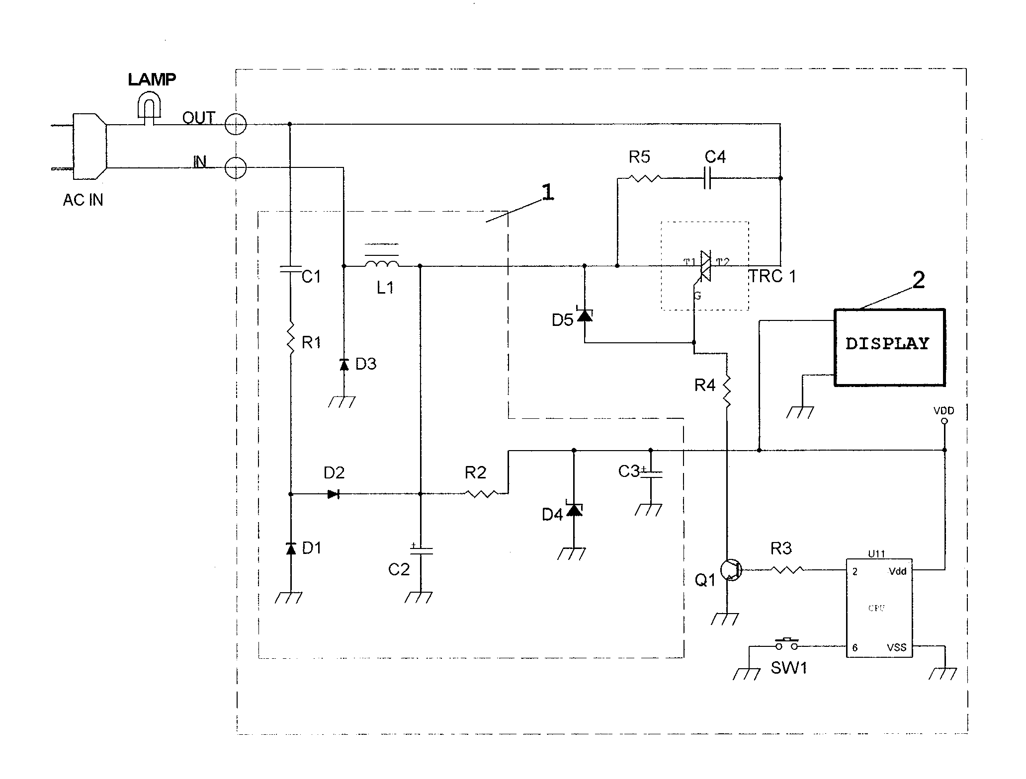
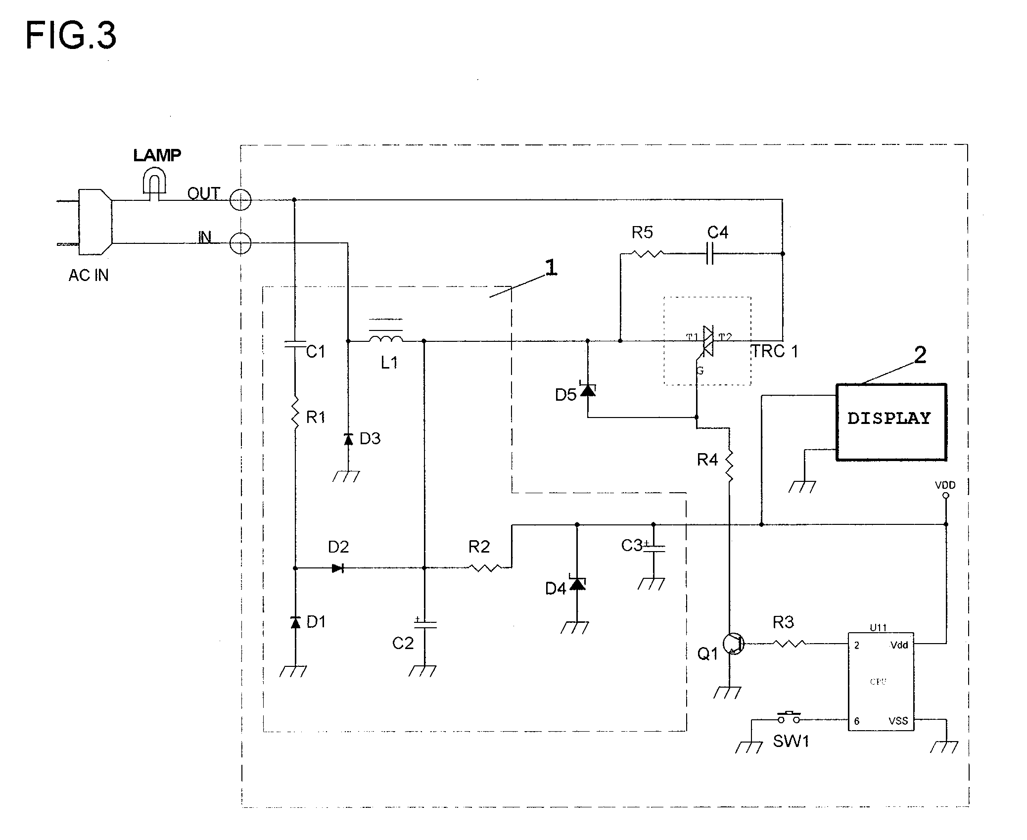
[0003]For this purpose, the characteristic of the invented “power supply circuit for wall-mounted electronic switches” is the inclusion of a step that uses a large part (30˜40%) of load current for driving the circuit when the load [Lamp] is on. Accordingly, using the invented “power supply circuit for wall-mounted electronic switches,” we can use a large part of load [Lamp] current as power for driving the circuit without a separate transformer for driving current out, and this simplifies the circuit, improves space utility, stabilizes the reliability of power supply, and contributes to price competitiveness.
Problems solved by technology
In the application, because the voltage of power for driving the circuit is very low as 5V and 5 mA, the circuit is not applicable to multi-functional switches of 5V and over 30 mA that use even LCD backlight.
Method used
View moreImage
Smart ImageViewing Examples

Examples
Embodiment Construction
[0032]As explained above, the invented “power supply circuit for wall-mounted electronic switches” simplifies the structure of power supply circuit for multi-functional power supply switches demanding a high driving current, stabilizes the operation of power supply circuit, improves the space utility of switches, and price competitiveness. FIG. 3 shows some desirable application examples, but the invention is not limited to this example and can be modified in various ways without changing the scope of this invention, and such modifications are within the application scope of this invention.
Login to View More PUM
 Abstract
This is a disclosure of a power supply circuit for wall-mounted electronic switches. The disclosed invention is about a power supply circuit for driving circuit inside the wall-mounted electronic switches, which can supply sufficient current demanded by these switch circuits. Recently the functions of wall-mounted electronic switches are being diversified from lamp switching to security, watch, remote control, room temperature control, etc. and the amount of current required inside the switch circuits is increased up to tens of mA. This requires a competitive power supply circuit that can supply a high current. In addition, a space-saving characteristic is also required because the space of a wall-mounted switch is narrow. The invented power supply circuit for electronic switches saves space, supplies a high current, and enhances competitiveness in price and quality, and consequently it makes a considerable contribution to the competitiveness of wall-mounted electronic switches.
Description
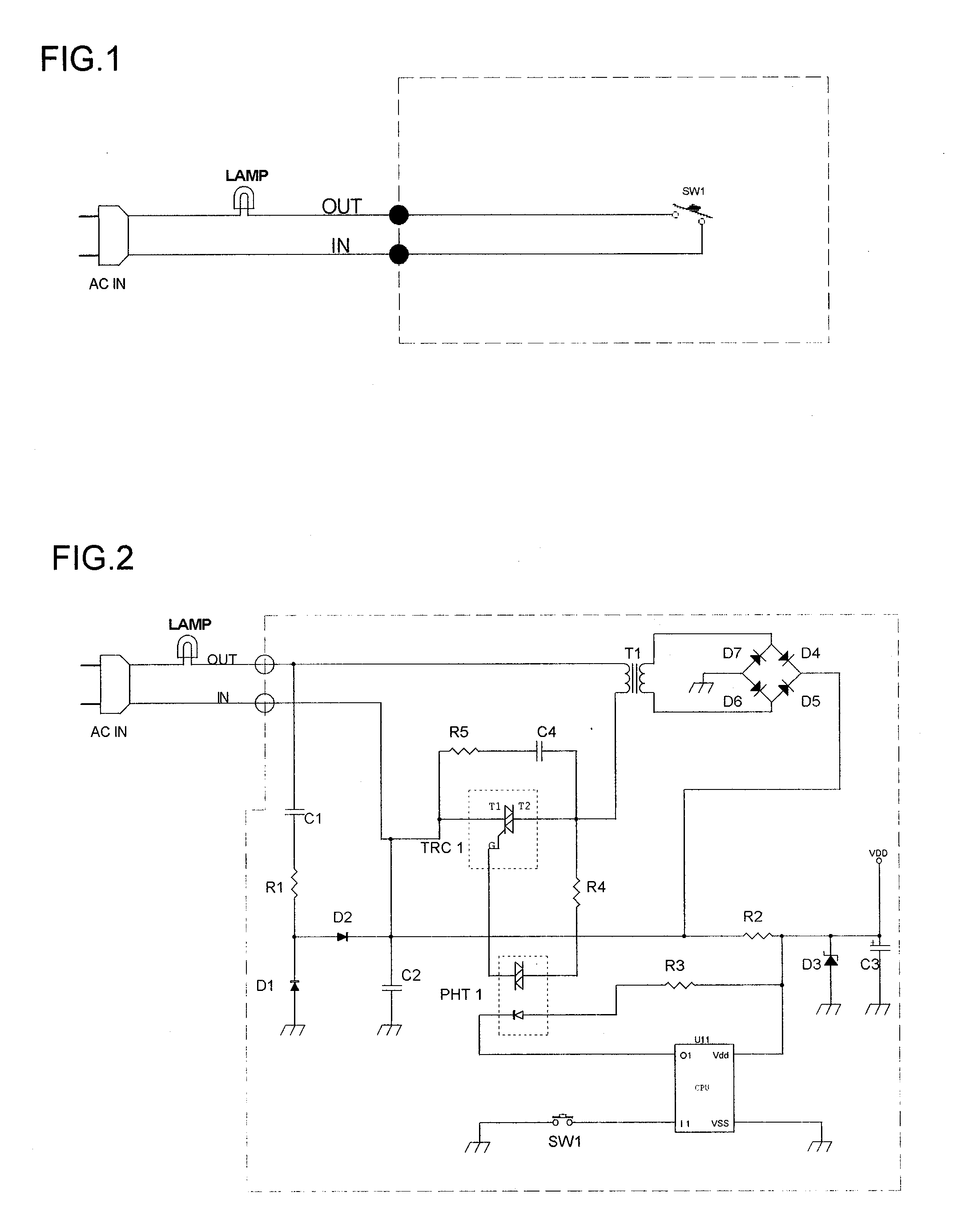
TECHNICAL FIELDS [0001]The present invention is “a power supply circuit for wall-mounted electronic switches” that enables the power supply for control circuit in wall-mounted electronic switches is realized space saving, high supply current, low cost, and high quality. Because an ordinary wall switch wire uses only one of the two AC power supply lines, which connect the objects like lamp on and off, as in FIG. 1, we used a separate transistor to drive out the current for internal circuitry of wall-mounted electronic switches as in FIG. 2. However, in case the load [Lamp] is under 20 W, current obtainable from the secondary side of transformer [T1] is only several mA. In order to raise it to tens of mA, the size of transformer [T1] should be very large and thus it was difficult to use the circuit as the power supply of switches that require high current. In addition, a conventional power supply circuit as in FIG. 2 was unstable in reliability because of its considerable variation of...
Claims
Login to View More Application Information
Patent Timeline
 IPC IPC(8): G05F1/10
CPCH02M5/08H02M7/12
InventorKIM, JIHN KUK
OwnerHAGA ELECTRONICS CO LTD