
A Structural Body, a Method for Forming a Structural Body, an Apparatus for Forming a Structural Body, a Method for Reading a Structural Color and/or Diffraction Light, and a Truth/False Discriminating Method

a structural body and a technology for detecting truth and false, applied in the field of structural bodies, can solve the problems of chemical color development using pigment substances that is unacceptable in view of recycling properties and environmental protection, and the development of structural colors to be artificially developed, so as to suppress the development of structural colors and high recycling properties

Inactive Publication Date: 2009-07-09
TOYO SEIKAN KAISHA LTD
View PDF4 Cites 38 Cited by
  • Summary
  • Abstract
  • Description
  • Claims
  • Application Information

AI Technical Summary

Benefits of technology

[0064]As mentioned above, according to the invention, a structural color satisfying the requirements for practical application on the industrial scale can be obtained.
[0065]Furthermore, the structural color of the invention can be effectively used for decorating plastic apparatuses or the like with a high degree of recycling properties.
[0066]In addition, since the cavity interface periodic structure or the substrate surface periodic structure are formed in the substrate itself, it is impossible to remove them for reuse. As a result, a damage caused by reusing it in a forgery, which occurs in the case of forgery protection seals, can be prevented.
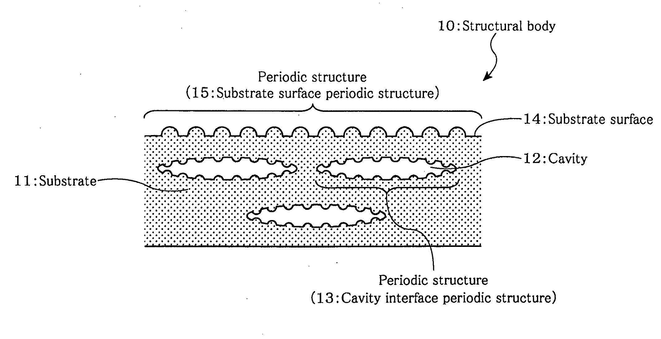
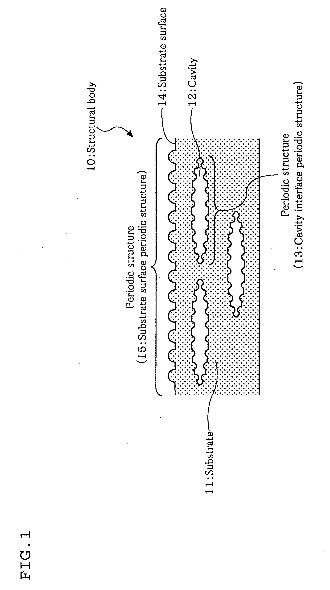
[0067]Furthermore, the cavity interface periodic structure is formed within the substrate, and the substrate surface periodic structure is formed on the surface of the substrate. Since each periodic structure develops a structural color, the structural color generated by the cavity interface periodic structure is hidden by the structural color generated by the substrate surface periodic structure.
[0068]In addition, by suppressing development of a structural color by bringing a functional material into contact with the substrate surface periodic structure, it is possible to read a shape formed by the structural color generated by the cavity interface periodic structure. Whether an object is genuine or not can be verified by comparing the shape which has been read with a shape for comparison. Accordingly, even a consumer can verify whether an object having a structural body is genuine or not by a simple method in which a functional material is brought into contact with the substrate surface periodic structure.

Problems solved by technology

In recent years, chemical color development using pigment substances has become unacceptable in view of recycling properties and environmental protection.
It is difficult to cause such a structural color to be developed artificially.

Method used


Image

  • A Structural Body, a Method for Forming a Structural Body, an Apparatus  for Forming a Structural Body, a Method for Reading a Structural Color and/or Diffraction Light, and a Truth/False Discriminating Method
  • A Structural Body, a Method for Forming a Structural Body, an Apparatus  for Forming a Structural Body, a Method for Reading a Structural Color and/or Diffraction Light, and a Truth/False Discriminating Method
  • A Structural Body, a Method for Forming a Structural Body, an Apparatus  for Forming a Structural Body, a Method for Reading a Structural Color and/or Diffraction Light, and a Truth/False Discriminating Method

Examples


example 1

[0245]By passing the light beam emitted from a Q-switch pulse YAG laser through a transmitting diffraction optical device, the light beam was divided into a plurality of light beams. Each of the light beams was caused to pass through a synthetic quartz flat convex lens with a focal length of 200 mm, which was placed 200 mm away from the transmitting diffraction optical device. At a position where the light beams which had passed the lens was focused, unnecessary light beams were hidden by a mask, thereby allowing only necessary light beams to pass through. The light beam which had passed through was focused by means of a synthetic quartz convex lens having a focal length of 100 mm. The light beam was caused to intersect and interfere. A biaxial elongated PET sheet was irradiated with the interference area. In advance, irradiation was performed with a laser beam having a wavelength of 355 nm (transmission for PET sheet of 83%).

[0246]Then, the wavelength was switched to 266 nm (transm...

example 2

[0255]A biaxial elongated PET sheet was irradiated with a laser having a wavelength of 266 nm in the same manner as in Example 1. A structural color was observed by the formed two-dimensional periodic structure.

[0256]To this periodic structure, an ester oil (CAS-Nr: 195371-10-9) having a refractive index of 1.518 which is close to that of the elongated PET sheet (1.64) was applied. As a result, the sheet was observed like the original transparent elongated PET sheet since no structural color was observed.


PUM

PropertyMeasurementUnit
diameteraaaaaaaaaa
distanceaaaaaaaaaa
periodic structureaaaaaaaaaa

Abstract

Decoration of a material is enabled with a high degree of recycling properties while satisfying the requirements for putting a structural color into practical use on the industrial scale. Furthermore, whether an object is genuine or not can be verified easily, and reusing by peeling as in the case of a hologram seal is prevented.A cavity 12 having a periodic structure 13 causing optical diffraction is formed in the inside of a substrate 11, and a periodic structure 15 causing optical diffraction is formed on part or the whole of the substrate 11. These cavity interface periodic structure 13 and the substrate surface periodic structure 15 have a regular arrangement developing a structural color. In addition, by bringing a functional material to be in contact with the substrate surface periodic structure 15, development of a structural color by the substrate surface periodic structure 15 is suppressed, thereby enabling a structural color developed by the cavity interface periodic structure 13 to be read.

Description

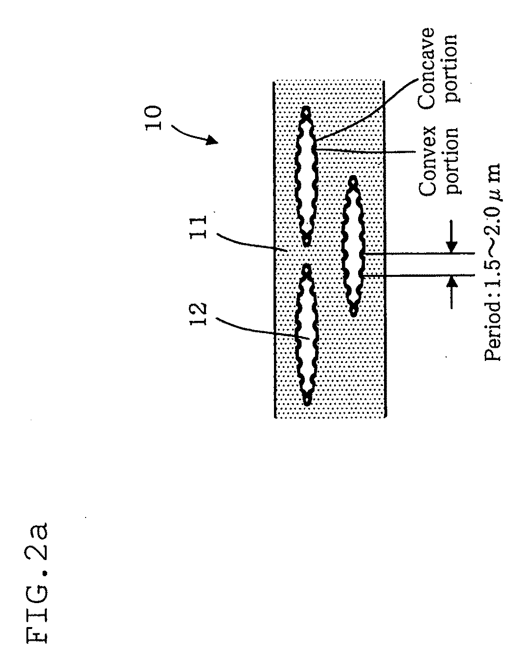
TECHNICAL FIELD[0001]The invention relates to a structural body having optical-control function utilizing optical phenomenon such as diffraction and interference, a method for forming the structural body, an apparatus for forming the structural body by executing this method, a structural color and / or diffraction light developed by this structural body, and a truth / false discrimination method using this structural body. In particular, the invention relates to a structural body which can be served as a marking having forgery-protection effects, which develops a structural color by a periodic structure formed in the interface of a cavity formed within the body, can prevent illegal reuse and facilitates truth / false verification, a method for forming a structural body, an apparatus for forming a structural body, a method for reading a structural color and / or diffraction light, and a truth / false discrimination method.BACKGROUND[0002]In recent years, chemical color development using pigmen...

Claims


Application Information

Patent Timeline
Patent Type & Authority Applications(United States)
IPC IPC(8): G02B27/44G02B5/18B29C67/20
CPCG02B5/1857G03H1/0011G03H1/0244G03H1/26B29C67/0007G03H2270/52G03H2270/54G07D7/0013G03H2001/0016G07D7/0032G02B5/18
Inventor YUASA, YOSHIYUKITAKENOUCHI, KEN
Owner TOYO SEIKAN KAISHA LTD
Learn More