
Mobile Communication System and Mobile Terminal

a mobile terminal and communication system technology, applied in the field of mobile communication systems, can solve the problems of limiting the available capacity of a mobile terminal in a mobile communications system, unable to make a transition to drx operation, heavy scheduling load, etc., and achieve the effect of efficient power consumption in the mobile terminal

Inactive Publication Date: 2009-07-16
MITSUBISHI ELECTRIC CORP
View PDF8 Cites 256 Cited by
  • Summary
  • Abstract
  • Description
  • Claims
  • Application Information

AI Technical Summary

Benefits of technology

[0066]As a result, there is provided an advantage of being able to efficiently achieve low power consumption in the mobile terminal.

Problems solved by technology

While, in general, the packet communication method is based on a continuous connection, there is a limit to the available capacity of a battery which a mobile terminal in a mobile communications system can carry.
However, the nonpatent references 1 to 3 and the patent reference 1 do not disclose any concrete method of effectively achieving low power consumption in a mobile terminal in a DRX / DTX operation period during Active (a state 2-B as shown in FIG. 13).
Furthermore, a problem with the method disclosed by the nonpatent reference 6 is that a base station has to carry out scheduling in order to determine a timing (i.e., a DRX period end timing) at which the base station starts a DRX operation every time when the base station receives a Nack signal from a mobile terminal (“a time (i)”, “a time (ii)”, and “a time (iii)” shown in FIG. 14), and therefore the load of the scheduling becomes heavy.
Therefore, a problem with the method of notifying the DRX cycle information by using an L1 / L2 control signal together with the first-time transmission data, notifying the DRX cycle information at a time of a setup of a radio bearer, or determining the DRX cycle information in advance, in a conventional way is that when retransmission based on HARQ exceeds this DRX cycle, it becomes impossible to make a transition to a DRX operation.
Furthermore, these references also disclose nothing about what kind of information is notified using a symbol available for a Unicast service in a subframe allocated to the E-MBMS.
Therefore, the throughput of the mobile terminal decreases, and, even if it is preferable to give a higher priority to the throughput of the mobile terminal than to achievement of low power consumption in the mobile terminal, any improvement in the throughput cannot be achieved.
Therefore, in accordance with the current technology, because a parameter showing which achievement of low power consumption in a mobile terminal or an improvement in the throughput of the mobile terminal should be given a higher priority is specific to each mobile terminal, and the timing at which a notification of the parameter can be made is restricted, it is difficult to effectively achieve low power consumption in the mobile terminal during a DRX / DTX operation period during Active (a state 2-B as shown in FIG. 13).
Because conventional mobile communications systems are constructed as mentioned above, they make it possible to introduce the state 2-B, i.e., a “DRX / DTX operation period during Active” into the state 2, in which the system is operating at an RRC level, i.e., an “Active (in a broad sense).” A problem is, however, that neither a method of efficiently achieving low power consumption in a mobile terminal nor a method of setting up DRX / DTX cycles is defined, and therefore low power consumption cannot be necessarily achieved efficiently in a mobile terminal.

Method used


Image

  • Mobile Communication System and Mobile Terminal
  • Mobile Communication System and Mobile Terminal
  • Mobile Communication System and Mobile Terminal

Examples


embodiment 1

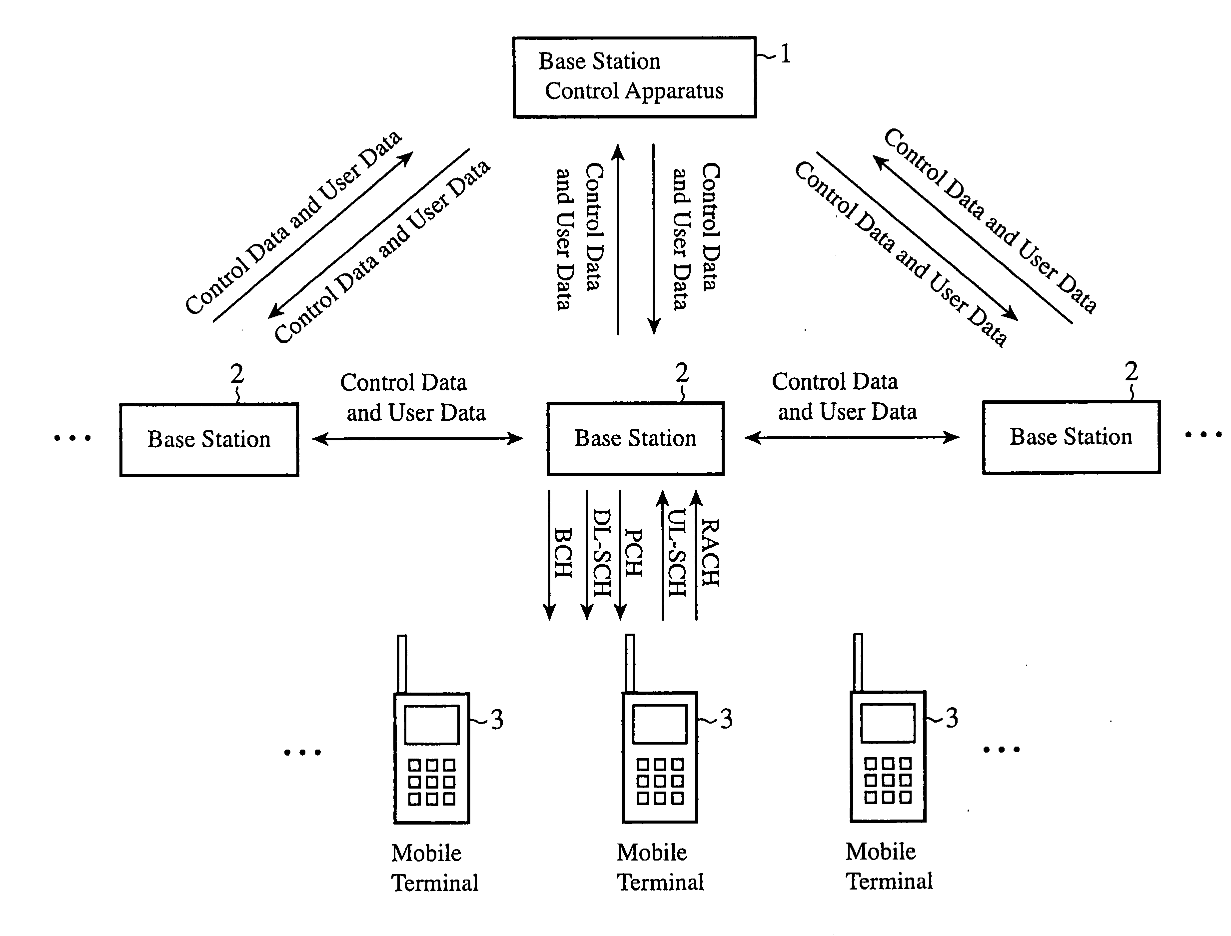
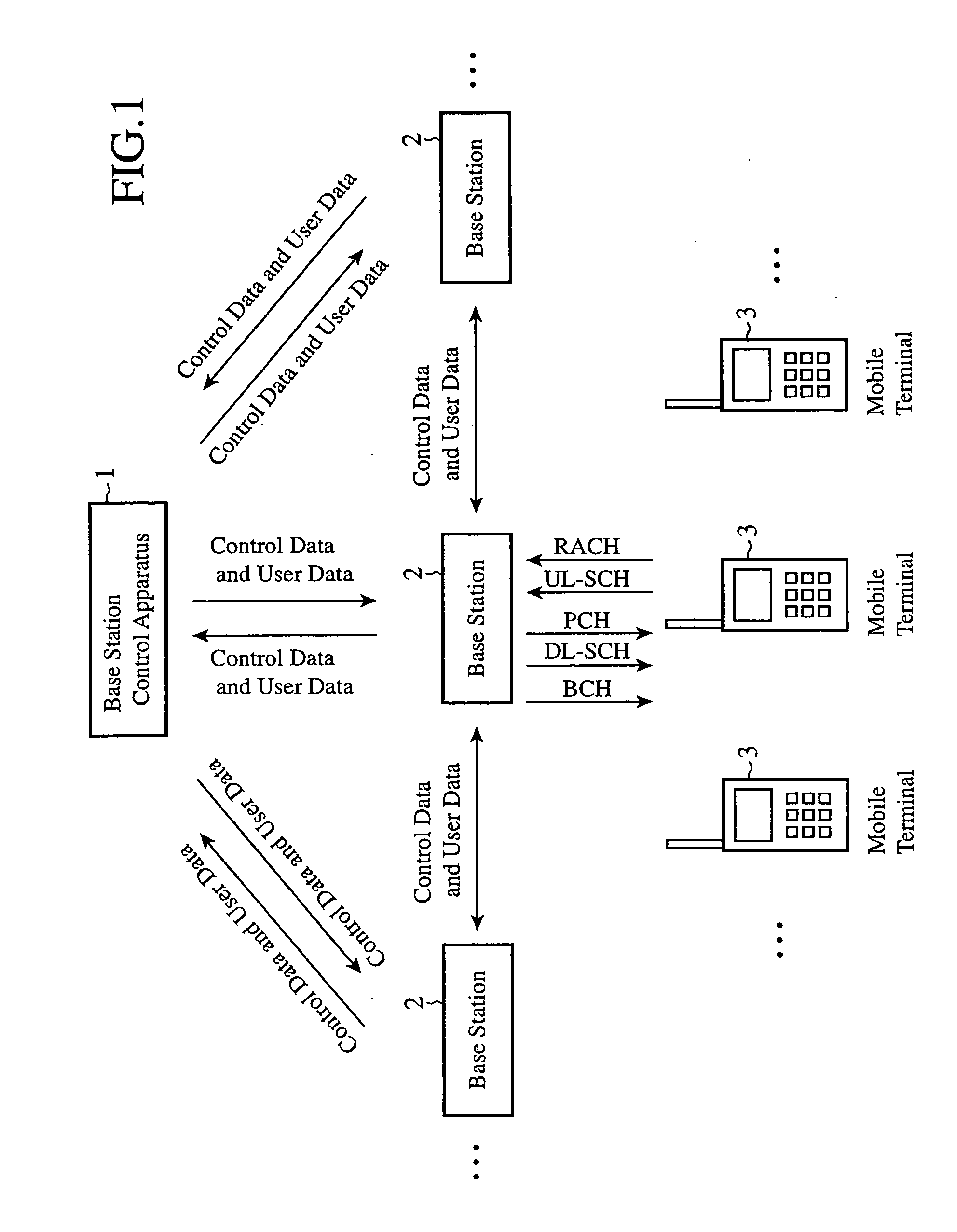
[0124]FIG. 1 is a block diagram showing a mobile communications system in accordance with Embodiment 1 of the present invention.

[0125]The mobile communications system of FIG. 1 is an LTE system, and an uplink scheduler and a downlink scheduler of a base station controls the transmission rate, the transmission power (the permitted transmission power and the maximum permitted transmission power), the transmission timing, the available frequency, the width of the available frequency, and so on of each of a plurality of mobile terminals.

[0126]Transport channels (Transport Channels) via which a mobile terminal and a base station communicate with each other in the mobile communications system of FIG. 1 will be further explained. Although it can be considered that the names and definitions of the transport channels will be changed from now on because the transport channels have been under debate, it cannot be overemphasized that the present invention can be applied to even a case in which ...

embodiment 2

[0344]FIG. 6 is a sequence diagram showing the description of processing carried out by a mobile communications system in accordance with Embodiment 2 of the present invention. Hereafter, the description of the processing carried out by the mobile communications system will be explained.

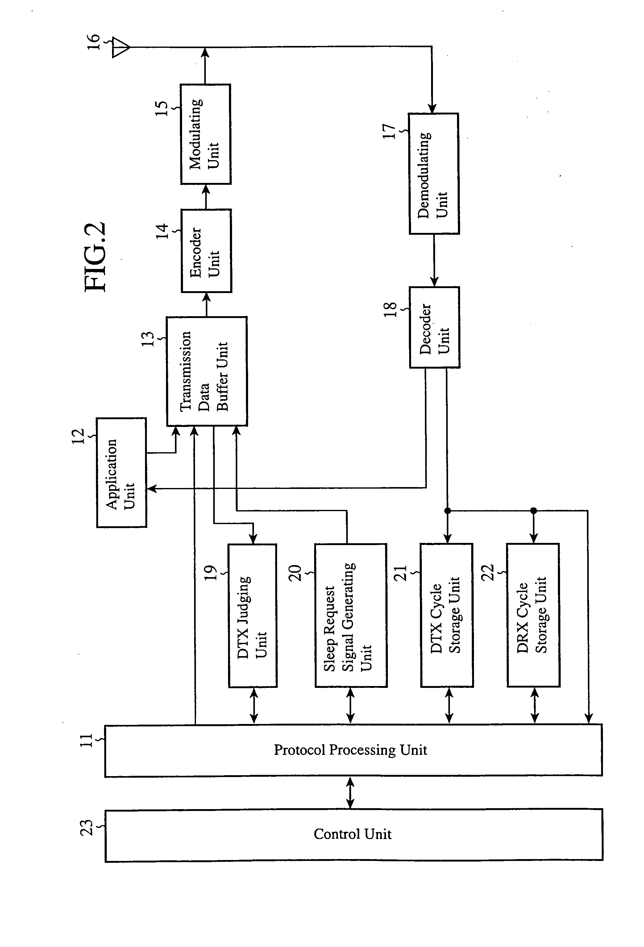
[0345]When judging that a mobile terminal 3 is able to perform a DRX operation during Active (in a broad sense) in the same way as that mentioned in Embodiment 1, a protocol processing unit 33 of a base station 2, when performing a DRX operation during Active (in a broad sense), determines both a DRX cycle used for the DRX operation during Active (in a broad sense) and a DTX cycle used for the DTX operation during Active (in broad sense) which are most suitable for reduction in the power consumption of the mobile terminal 3 (step ST31).

[0346]In this case, the most suitable DRX cycle and DTX cycle are the ones which lengthen a time period during which the electric power supply of the transmission proc...

embodiment 3

[0439]FIG. 8 is a sequence diagram showing the description of processing carried out by a mobile communications system in accordance with Embodiment 3 of the present invention.

[0440]In above-mentioned Embodiments 1 and 2, the example in which a base station 2 determines whether or not a mobile terminal 3 is able to make a transition to a DTX operation period during Active, and, when the mobile terminal is able to make a transition to a DTX operation period during Active, the mobile terminal temporarily stops the supply of the electric power to the data transmission processing units and the data reception processing units thereof if the base station 2 determines that the mobile terminal 3 is able to make a transition to a DTX operation period during Active is shown. The protocol processing unit 11 of the mobile terminal 3 can determine whether to give a higher priority to low power consumption (or can determine whether to give a higher priority to throughput), and can transmit a para...


PUM


Abstract

A mobile terminal judges whether or not the mobile terminal is able to make a transition to a DTX period during Active, and, when judging that the mobile terminal is able to make a transition to a DTX period during Active, notifies a base station to that effect. If the base station judges that the mobile terminal is able to make a transition to a DRX period during Active when triggered by the notification from the mobile terminal, the base station temporarily stops supply of electric power to the data transmission processing units and the data reception processing units of the mobile terminal.

Description

FIELD OF THE INVENTION[0001]The present invention relates to a mobile communications system in which a base station carries out radio communications with a plurality of mobile terminals by controlling the transmission rates, the transmission powers (the permitted transmission powers and maximum permitted transmission powers), the transmission timings, the available frequencies, and so on of the plurality of mobile terminals, by using a scheduler, and a mobile terminal which constructs the system.BACKGROUND OF THE INVENTION[0002]In recent years, the mainstream of a data communication method which a mobile communications system uses has been changing from a circuit switching method to a packet communication method.[0003]While, in general, the packet communication method is based on a continuous connection, there is a limit to the available capacity of a battery which a mobile terminal in a mobile communications system can carry.[0004]Therefore, in a case in which the mobile communicat...

Claims


Application Information

Patent Timeline
IPC IPC(8): G08C17/00H04W52/02H04W76/28
CPCH04W52/028H04B7/2643H04W52/0216H04W76/28H04W52/0229Y02D30/70H04L1/0027H04W8/22H04W72/04
Inventor MAEDA, MIHOMOCHIZUKI, MITSURUIWANE, YASUSHIMISHUKU, TETSUYAKUSANO, MASAAKIFUJIE, RYOICHITANI, SHIGENORITADA, KEIKOFUKUI, NORIYUKITAKANO, MICHIAKI
Owner MITSUBISHI ELECTRIC CORP
Learn More