Video/Audio Reproducing Apparatus

a video/audio and apparatus technology, applied in the field of apparatus for reproducing video and/or audio, can solve the problems that the delay amount cannot be determined uniformly, and it is difficult for the user of the audio/video transmission system to achieve the adjustment, so as to achieve the synchronization between the outputs of video and audio, and achieve the effect of easy synchronization

Inactive Publication Date: 2009-07-16
HITACHI LTD
View PDF6 Cites 34 Cited by
  • Summary
  • Abstract
  • Description
  • Claims
  • Application Information

AI Technical Summary

Benefits of technology

[0009]With such the means mentioned above, it is possible to achieve the synchronization between outputs of the video and the audio, easily.

Problems solved by technology

However, there are sometimes cases where it is difficult for the user of the audio / video transmission system to achieve the adjustment from a beginning, in particular, so as to obtain the synchronization for the video and the audio, which are shifted greatly.
Also, the delay amount cannot be always determined uniformly depending upon the transmission rate.

Method used


Image

  • Video/Audio Reproducing Apparatus
  • Video/Audio Reproducing Apparatus
  • Video/Audio Reproducing Apparatus

Examples


embodiment 1

[0040]

[0041]First of all, the structural examples of a receiving apparatus and peripheral equipments thereof will be explained by referring to FIGS. 1 to 11.

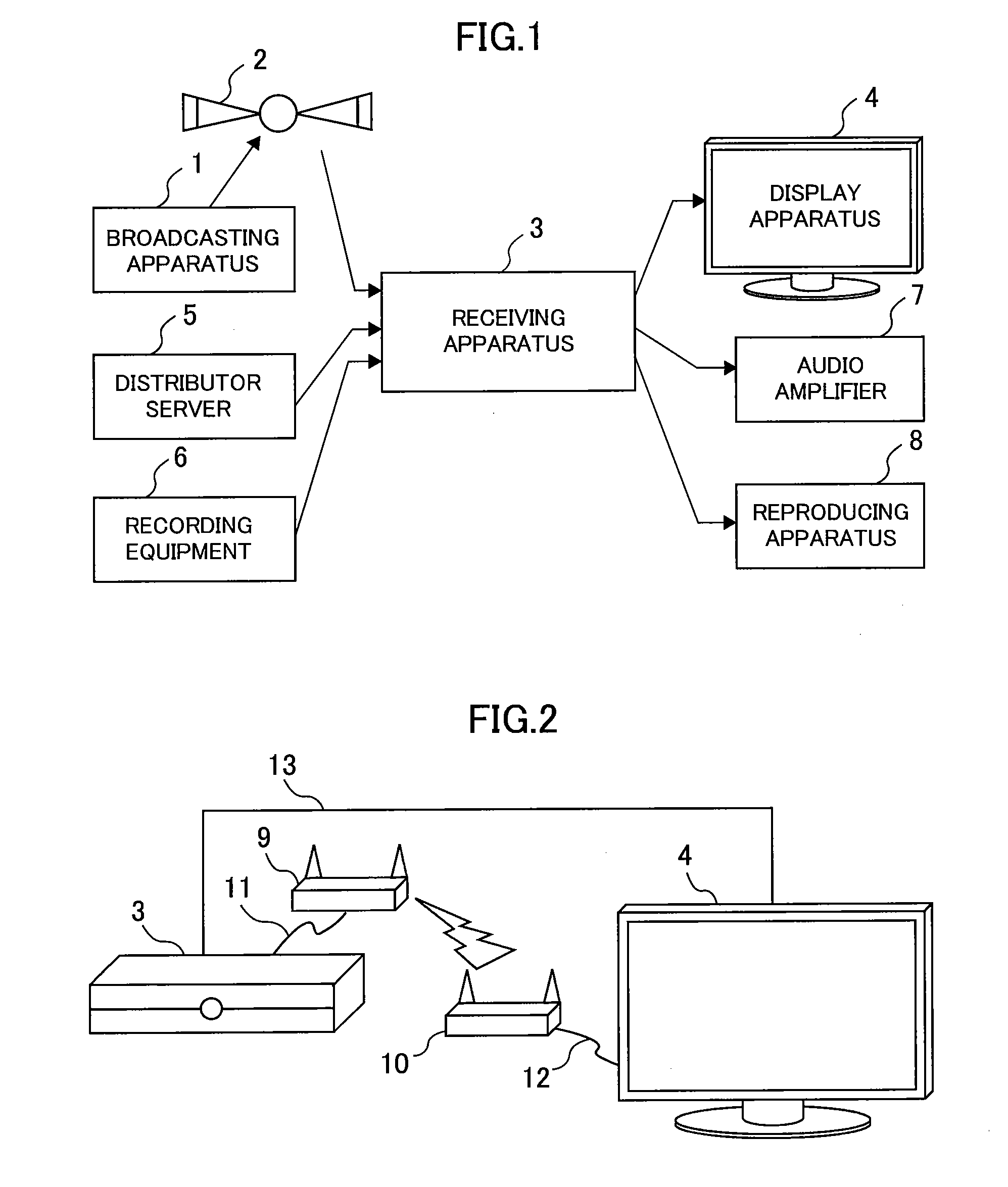
[0042]FIG. 1 is a view for showing an example of data input / output of the receiving apparatus. A reference numeral 1 depicts a broadcasting station. A reference numeral 2 depicts a broadcasting satellite. There is the receiving apparatus 3 for receiving a signal transmitted from the broadcasting satellite, and it conducts processes, such as, expanding data compressed, etc., thereby to output to a display apparatus 4. Other than broadcast waves, various modes can be considered as the input, i.e., it is possible to receive a signal, which the broadcasting station transmits through a terrestrial wave. Or, there can be considered the followings, such as, receiving from a distribution server 5, which transmits data through a network, such as, Internet, etc., or receiving from a video recording equipment, which is connected through a ...

example 2

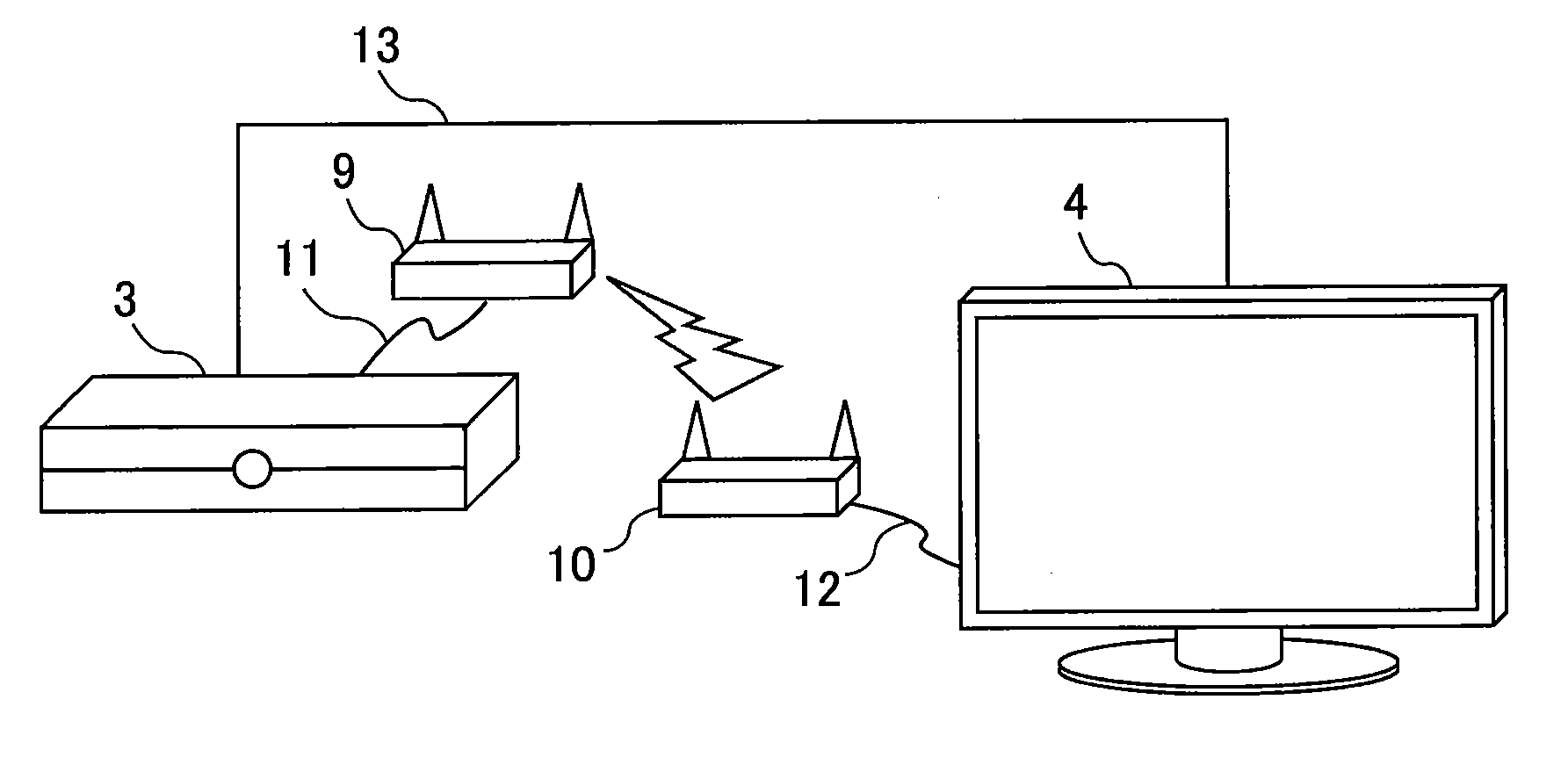
[0115]Consideration is paid on a case where the video and the audio differs from in the transmission time on the data transmission between the receiving apparatus 3 and the display apparatus 4, but without provision of the delay portions 506 and 605, or 805 and 905. Also, in this case, if time difference is determined, uniquely, in advance, depending on the transmission unit, then the controller portion 320 makes the correction or compensation thereof within the delay portion 307 or the offset supply portion 1102. A method, for example, for obtaining that transmission time difference, automatically, will be shown below.

[0116]Within the wireless or radio signal transmitter portion 312, a time stamp is added onto the data of video and audio, which will be transmitted at a predetermined timing. Within the wireless or radio signal receiver portion 404, the value of the time stamp added is obtained, and the difference thereof is calculated within the controller portion 408. It is possibl...

example 3

[0117]In the embodiment 1, though the explanation was given on the method for delaying the audio output, however it is also possible to adjust or shift the timing of the decoding process of the video data front and back, by applying the offset to PTS. For example, when the audio, which is optically outputted, is delayed at the output, i.e., within the audio amplifier 7 at the destination of the output, it is possible to obtain the synchronization by setting an appropriate offset to PTS.


PUM


Abstract

A video/audio reproducing apparatus, to be connected via a first apparatus with a second apparatus, comprises: a first receiving portion, which is configured to receive video data, audio data, and first reproduction synchronization information for reproduction synchronization between the video data and the audio data; a second receiving portion, which is configured to receive second reproduction synchronization information for reproduction synchronization between the video data and the audio data from the first apparatus; and a controlling portion, which is configured to reproduce the video data and the audio data received by the first receiving portion, upon basis of the first reproduction synchronization information and the second reproduction synchronization information, which are received by the first receiving portion and the second receiving portion.

Description

BACKGROUND OF THE INVENTION[0001]The technical field of the present invention relates to an apparatus for reproducing video and / or audio.[0002]In relation with the technical field mentioned above, within the following patent document 1 is described “to provide an audio / video transmitting apparatus for enabling to reduce the difference between the audio reproduced and the video reproduced, caused due to the fact that an audio signal and a video signal are transmitted, respectively, through different transmission devices, although reproduction timings of them should be fitted with each other”, as a problem, and as a dissolving means thereof, “although from the audio / video transmission apparatus, the video signal is transmitted through radio from a video radio transmitting portion while the audio signal is transmitted with wire from an audio outputting portion, but in this case, an adjustment is made by delaying the audio signal, by means of an audio delaying portion provided in the au...

Claims


Application Information

Patent Timeline
Patent Type & Authority Applications(United States)
IPC IPC(8): H04N7/087H04N7/173H04N7/52
CPCH04N5/04H04N21/2368H04N21/4305H04N21/4622H04N21/4341H04N21/4363H04N21/4405H04N21/4307H04N21/43072
Inventor KANEMARU, TAKASHITSURUGA, SADAO
Owner HITACHI LTD
Why Eureka
Try Eureka