[0017]The first connector can be flexible, partial flexible or rigid. A flexible or partially flexible connector serves for a facilitated application of a cable to be connected to the first connector. This is advantageous when using the preassembled tubular splice in a narrow space.
[0019]In the tubular terminal of the present invention, a cable can very easily be connected to the first connector. The first connector is fixedly connected and arranged within the shrinkable sleeve. A cable attached to a
mating second connector can be easily connected to the first connector in that the mating second connector is inserted into the second tubular portion of the shrinkable sleeve so as to make
electrical connection with the first connector by simply plugging in the second connector into the first connector, or vice versa. Accordingly, the shrinkable sleeve does not need a parking position or any
free space on one of the sides of the first connector. If the pre-assembled tubular terminal is used for connecting two
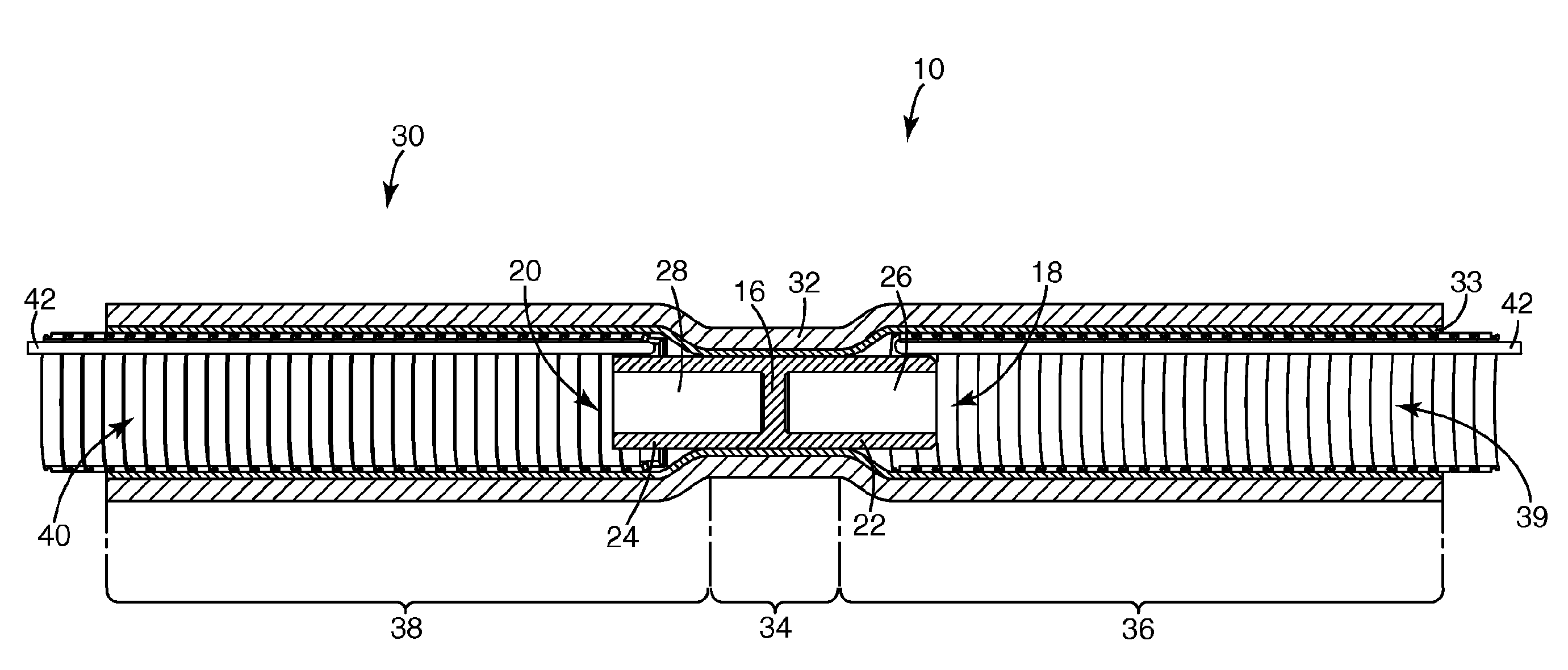
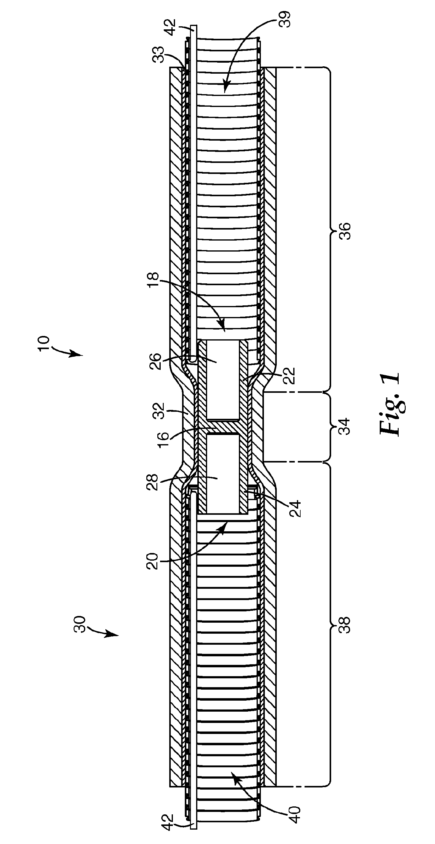
electric cables, both cables, with their associated mating second connectors attached, are inserted from opposite sides into the respective second tubular portions of the shrinkable sleeve or shrinkable sleeves. Namely, if the first connector is provided with two terminal ends at its opposite ends, the respective second tubular portions extend beyond both terminal ends of the first connector. As an alternative, two shrinkable sleeves overlapping each other can be fixedly arranged on the first connector with their respective second tubular portions extending beyond the terminal ends of the first connector.
[0023]In another embodiment of the present invention, the second tubular portion of the shrinkable sleeve is held in its radially expanded state by at least two cores arranged adjacent to each other. These two cores can be separated or flexibly connected in order to provide bendability of the second tubular portion of the shrinkable sleeve for facilitating the connection between the first and second connectors. The at least two cores may have different inside diameters, which further may facilitate the application and use of the pre-assembled tubular terminal according to the present invention.
[0027]In another embodiment of the present invention, the second shrinkable sleeve has a second tubular portion within which the second shrinkable sleeve is wound up so as to form a circumferentially extending roll arranged on the first tubular portion of the first shrinkable sleeve and / or its second tubular portion. If the first shrinkable sleeve comprises a third tubular portion, the second shrinkable sleeve may also comprise a third tubular portion which is wound up similar to its second tubular portion and is arranged on the first tubular portion and / or the third tubular portion of the first shrinkable sleeve. Each circumferentially extending roll of the second shrinkable sleeve may be fixed and secured so as to prevent the roll from unwinding. In particular, if the second (and third, if provided) tubular portion of the first shrinkable sleeve is held in a radially expanded state, the widening section between the first and second (and the first and third) tubular portions of the first shrinkable sleeve will prevent or will help to prevent the roll or rolls from inadvertently unwinding.
[0030]In a further embodiment of the invention, a
radio frequency identification (RFID) tag may be integrated into the tubular terminal. Such RFID tag can save information about the parts it is related to, you can write information on the RFID tag during the
life time of the parts it is related to and you can read the information saved on the RFID tag. The RFID tag can be integrate in the tubular terminal of the invention during the production. At that time the first information can be added on the tag like information about the connector, production date etc. A preferred location for the integration of the RFID tag would be the area above the first connector, especially where the first and second shrinkable sleeves are fixedly arranged around the first connector, which means that there is a constant
radial pressure between the shrinkable sleeve and the connector. That would have the
advantage that no
mechanical pressure like extending, stretching or compressing will be applied to the tag during the installation and that no additional work steps are necessary during the installation to integrate the tag. The tag can be integrated within one of the sleeves either the first or the second shrinkable sleeve. It is important that the tag will not be integrated underneath a layer with shielding characteristics.

