
Knee immobilizer

a knee and immobilizer technology, applied in the field of orthopaedic braces, can solve the problems of levee being bent backwards, increasing rotation, damage or tear of supporting ligaments, etc., and achieves the effects of reducing the pistoning of the brace, enhancing the strength of the popliteal region, and increasing the support level

Inactive Publication Date: 2009-07-16
OSSUR HF
View PDF55 Cites 33 Cited by
  • Summary
  • Abstract
  • Description
  • Claims
  • Application Information

AI Technical Summary

Benefits of technology

The present invention is a knee immobilizer that has an adjustable length for supporting the leg of a patient. It includes an elongated stay member, femoral and tibial cuffs, and a liner that at least partially envelops the leg. The femoral and tibial cuffs are designed to wrap around the cradle the muscle bellies of the leg, providing increased support with fewer straps and no medial or lateral stays. The stay member has an engineered geometric shape that wraps around the leg and provides all the immobilization necessary without the need for articulation or hinge. The sliding cuff-posterior stay assembly allows for length adjustment and can be custom tailored to fit the patient's leg. The foam liner is removable and can be trimmed or colored for different patients. The brace is cooler to wear in warm climates, has a lower profile, and reduces pistoning.

Problems solved by technology

If enough force is applied to the knee this rotation will increase and damage or tear the supporting ligaments.
Damage can also result from the levee being bent backwards (hyperextension).
In many cases, simple rest is inadequate and surgery may be required to repair the damage.
For example, they have a multitude of straps that make the knee brace confusing to use and time consuming to apply.
Finally, conventional knee braces are not size / color adjustable so that medical practices must stock a multitude of sizes and colors as needed to fit the varying anatomy of their patients.

Method used


Image

  • Knee immobilizer
  • Knee immobilizer
  • Knee immobilizer

Examples


Embodiment Construction

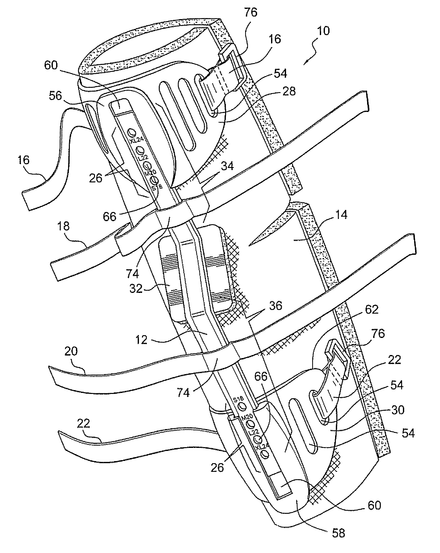
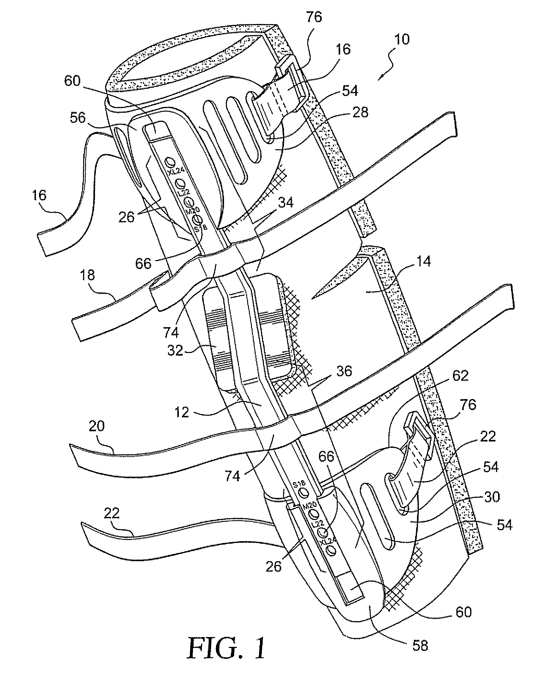
[0025]The present invention is directed to an orthopedic brace for support of an injured limb. In the preferred embodiment, the present invention is directed to a knee immobilizer. As seen in the perspective view of FIG. 1, the knee immobilizer or brace 10 is preferably constructed of a rigid support structure 12 acting as a spine and incorporates an optional foam compressive liner 14 and a strapping system consisting of four straps 16, 18, 20, 22. As seen in FIG. 9, the knee immobilizer or brace 10 is shown in normal use. It is attached to the posterior portion of a patient's leg 24.

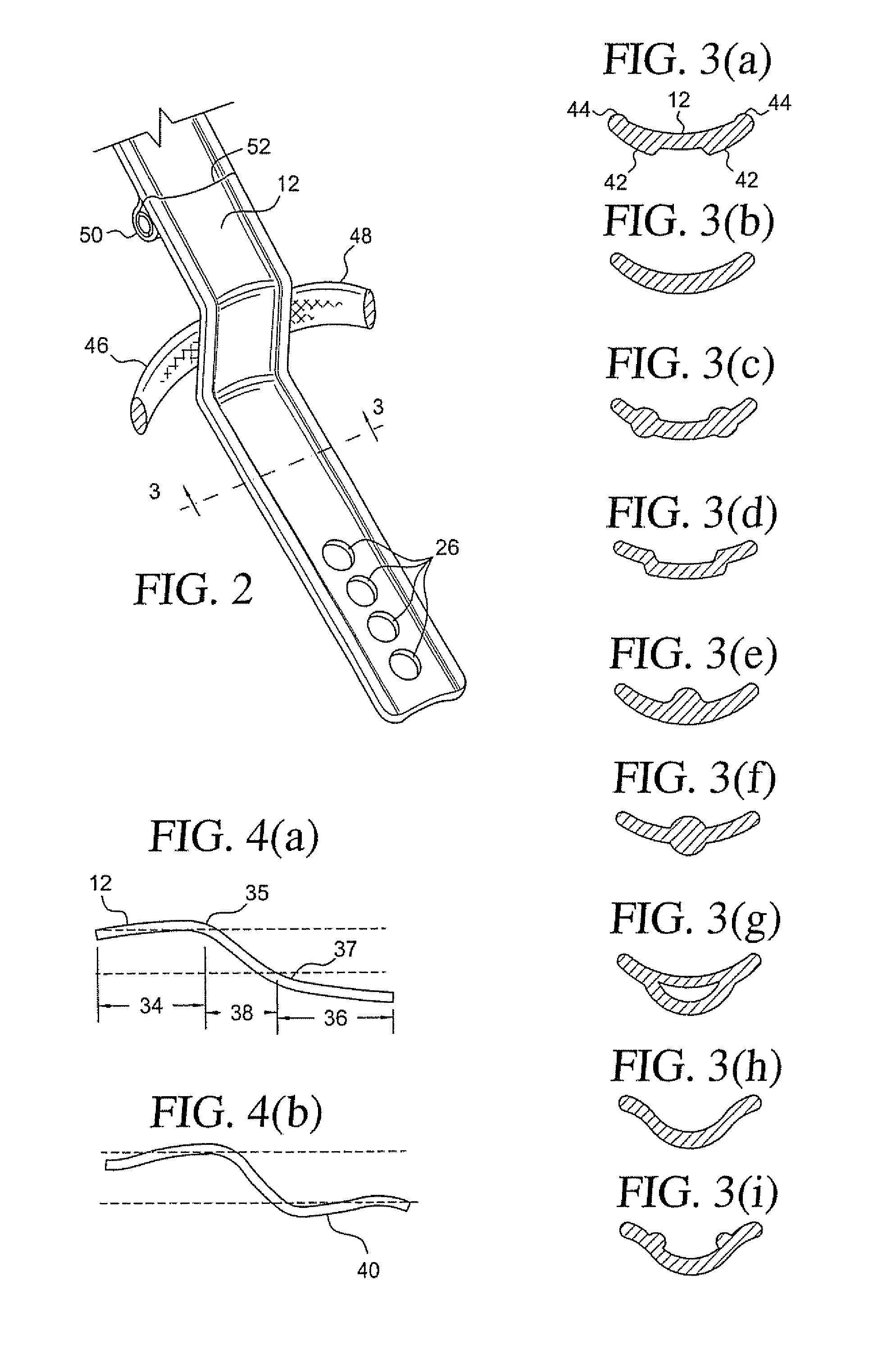
[0026]In FIG. 1, at the top and bottom ends of the stay member 12 are the femoral and tibial cuffs 28, 30, respectively. The cuffs 28, 30 slide along the femoral and tibial portions 34, 36 of the stay member 12 for quick adjustment of its overall length. An optional popliteal pad 32 is attached to the stay member 12 to further provide support and protect the very sensitive popliteus area of the knee. Th...


PUM


Abstract

An orthopedic brace designed to immobilize the knee by preventing flexion / extension and limiting medial / lateral movement. The brace includes a main support structure embodied in a unitary, rigid stay member with slidable, semi-rigid cuffs at one or both ends to provide length adjustability. The stay member has no popliteal articulation in order to immobilize the knee joint, and further provides attachment for a Velcro strapping system for easy application to the posterior of the leg. A breathable foam softgood insulates the leg and knee from the main support structure and strapping system yet is completely detachable from the brace so it can be trimmed to any desired length or width, and washed as necessary.

Description

[0001]This application claims the benefit of priority from U.S. application Ser. No. 11 / 035,133, filed Jan. 12, 2005.BACKGROUND OF THE INVENTION[0002]The present invention is directed to an orthopedic brace. More precisely, the present invention is directed to a knee immobilizer.[0003]The knee is probably the least protected joint in the human body. There is no ball and socket or mortice to hold the ends of the femur and tibia in their place. There are simply a few ligaments to hold everything together. Yet the knee carries the weight of our bodies and thus is subject to more forces than any other join in our anatomy.[0004]The knee allows free flexion and extension of the lower leg and limited medial and lateral movement (rotation). If enough force is applied to the knee this rotation will increase and damage or tear the supporting ligaments. Damage can also result from the levee being bent backwards (hyperextension).[0005]Once damage is done to the ligaments, the injured tissue nee...

Claims


Application Information

Patent Timeline
Patent Type & Authority Applications(United States)
IPC IPC(8): A61F5/00
CPCA61F5/0585
Inventor GRIM, TRACY E.WYATT, STACYIGLESIAS, JOSEPH M.LEE, WENDEECOBAR, HUGO A.
Owner OSSUR HF
Learn More