Instrument set for fitting an intervertebral jont prosthesis

a technology for intervertebral joints and instruments, applied in the field of fitting an intervertebral joint prosthesis, can solve the problems of unsuitable arrangement, difficult to imagine the precise positioning of the protective sleeve, and the inability to precisely align and position the intervertebral prosthesis through such a protective sleeve, so as to achieve the best possible visual control and high degree of precision

Inactive Publication Date: 2009-07-16
CERVITECH INC
View PDF56 Cites 30 Cited by
  • Summary
  • Abstract
  • Description
  • Claims
  • Application Information

AI Technical Summary

Benefits of technology

[0009]The object of the invention is to make available an instrument set for preparing the cervical spine for fitting an intervertebral joint prosthesis, said instrument set permitting a high degree of precision and the best possible visual control.
[0010]The instrument set of this invention has a guide device which is connected to the vertebral bodies concerned. It can be used to fix them in the desired relative position. It can also be used for guiding a tool for working the surfaces of the vertebral bodies. To arrange it with precision, an adjustment instrument is used which comprises an intervertebral plate. After the intervertebral disk and possibly the ventral protrusions of the upper vertebral body h

Problems solved by technology

For fitting an intervertebral prosthesis, such an arrangement is unsuitable for several reasons.
On the other hand, it is difficult to imagine an intervertebral prosthesis being precisely oriented and positioned by way of such a protective sleeve.
Because of its size, the protective sleeve would also greatly obstruct the view of the site.
This has the disadvantage that the milling block obstructs the operating surgeon's view of the distractor blade when the distractor blade is pushed into the intervertebral space.
It is therefore difficult to precisely position the known device.
For fitting intervertebral joint prostheses, however, such an arrangement cannot be used because the obst

Method used


Image

  • Instrument set for fitting an intervertebral jont prosthesis
  • Instrument set for fitting an intervertebral jont prosthesis
  • Instrument set for fitting an intervertebral jont prosthesis

Examples


Embodiment Construction

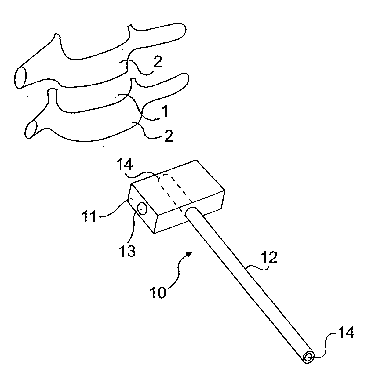
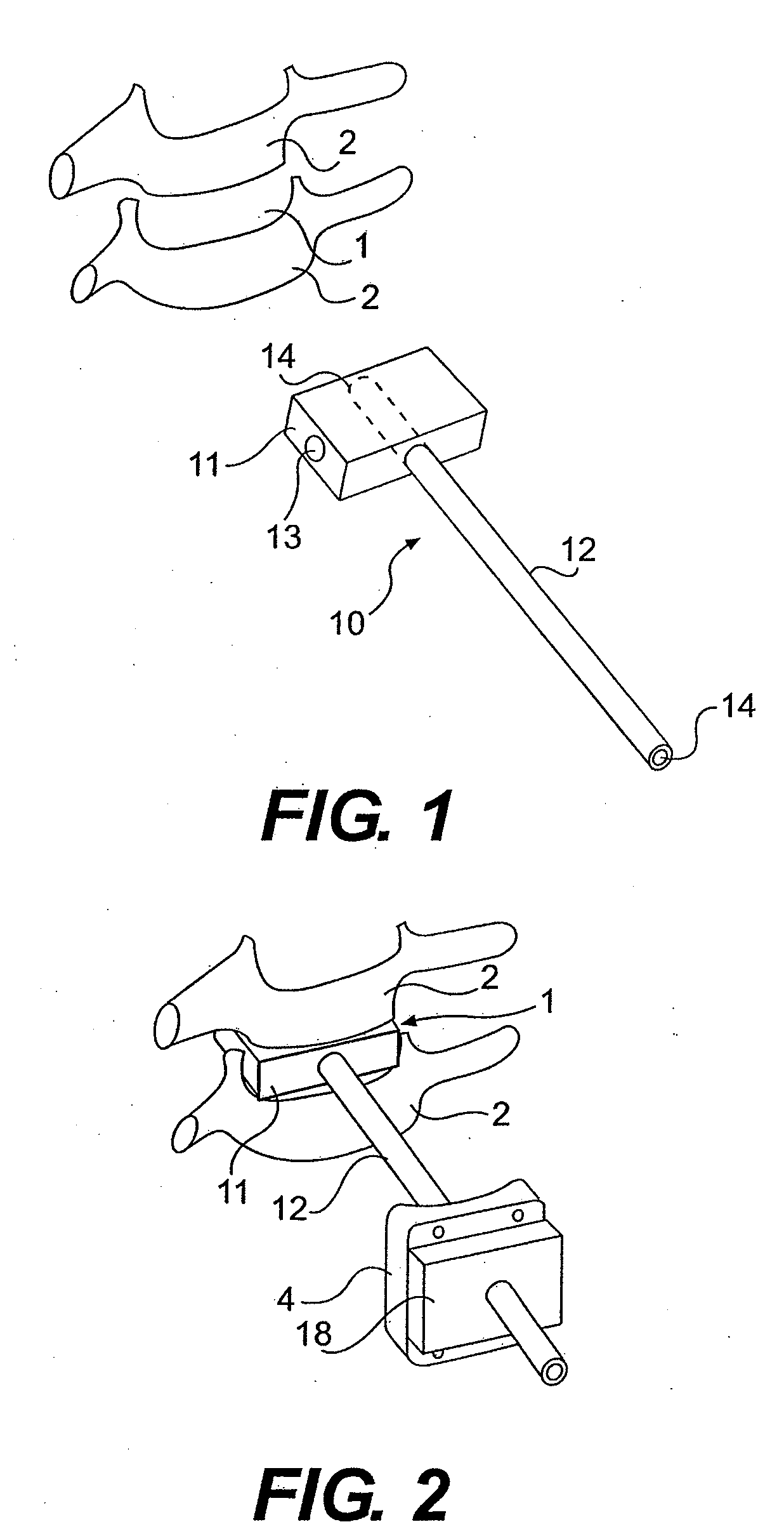
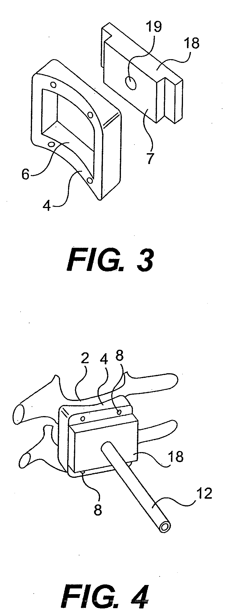
[0046]According to FIGS. 1-5, an intervertebral joint prosthesis is to be inserted into the intervertebral space 1 of the vertebral bodies 2. To do so, those faces of the vertebral bodies 2 facing one another have to be worked. Sensitive areas lie close by. To minimize the risks associated with the preparatory work, a machining gauge 3 is to be used which can be secured on the vertebral bodies 2 at a predetermined position. This is done using the guide device 4. The latter is frame-shaped with an opening 6 which is designed to match a projection 7 on the gauge 3. It is to be secured on the vertebral bodies 2 by means of pins 8. This has to be done with a high level of precision. By virtue of its frame shape, it is very flat, with the result that it does not impede visual monitoring and can also be used in a confined operating site.

[0047]For positioning it, the adjustment instrument 10 is provided. It comprises an intervertebral plate 11 and an adjustment rod 12 connected rigidly to ...


PUM


Abstract

An instrument set for fitting an intervertebral prosthesis includes a guide device for an instrument or a prosthesis part, which guide device is to be secured on at least one vertebral body. In order to attach the guide device precisely on the vertebral bodies despite difficult operating conditions, an adjustment instrument is provided which positions the guide device when this is being arranged on the vertebral body. This adjustment instrument may include an intervertebral plate which is fitted into the intervertebral space so as to be positioned exactly in relation to the vertebral bodies.

Description

REFERENCE TO RELATED APPLICATIONS[0001]This application is a continuation of U.S. application Ser. No. 10 / 731,432, filed Dec. 10, 2003, which is a continuation-in-part of U.S. application Ser. No. 10 / 357,516, filed Feb. 4, 2003, now abandoned, which claims priority from European Application No. 02 005 629.7, filed Mar. 12, 2002, the contents of which are herein incorporated in their entireties.FIELD AND BACKGROUND OF THE INVENTION[0002]When fitting an intervertebral joint prosthesis as a replacement for an intervertebral disk, the operating surgeon is working in an operating site which is very difficult to see and which is in immediate proximity to important nerve paths and blood vessels. This applies in particular to the area of the cervical spine, because here the dimensions of the vertebrae are very small and there is particularly little distance to sensitive adjoining areas. Therefore, in the case of instruments which pose a particular risk of damage or which have to be inserted...

Claims


Application Information

Patent Timeline
IPC IPC(8): A61B17/58A61B17/00A61B17/02A61B17/17A61B17/70A61F2/44A61F2/46H05K13/08
CPCA61B17/1757A61B17/7059A61B2017/00261A61B2017/0256A61F2002/4475A61F2/4455A61F2/4611A61F2/4657A61F2/4684A61F2/442A61F2002/30593
Inventor LINK, HELMUT D.KELLER, ARNOLDMCAFEE, PAUL C.
Owner CERVITECH INC
Why Eureka
Try Eureka