
Temperature controlling device of heating element and method thereof

a technology of temperature control device and heating element, which is applied in the direction of heat measurement, instruments, digital computer details, etc., can solve the problems of slow re-rising of temperature, inability to determine the work status of the heating element and the thermal requirement of the heated object, and the temperature of the electric soldering iron may fall rapidly, so as to prolong the life time of the electric heating element, save electric power, and efficiently and quickly control the electric power

Active Publication Date: 2009-07-16
L LAB
View PDF10 Cites 7 Cited by
  • Summary
  • Abstract
  • Description
  • Claims
  • Application Information

AI Technical Summary

Benefits of technology

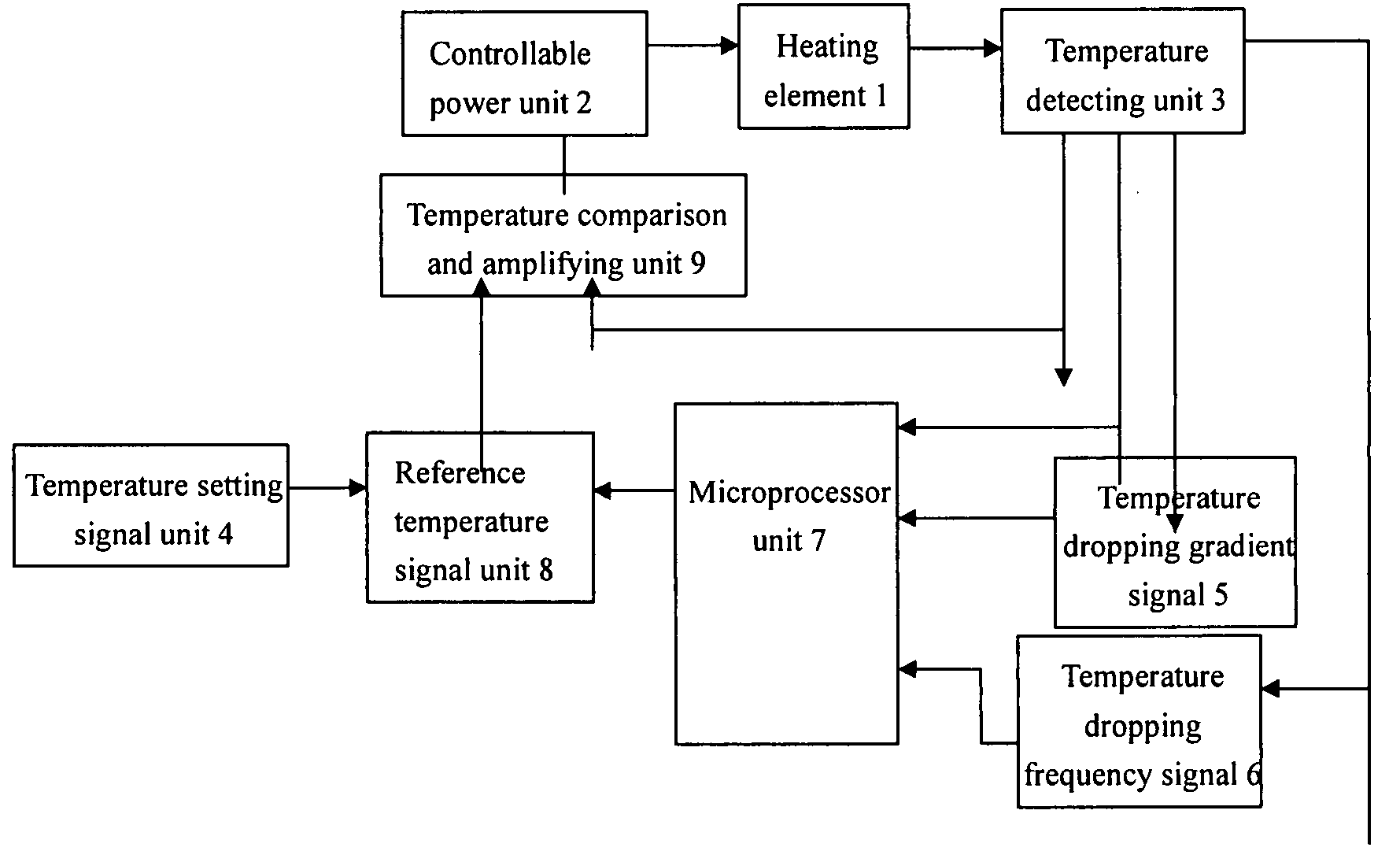
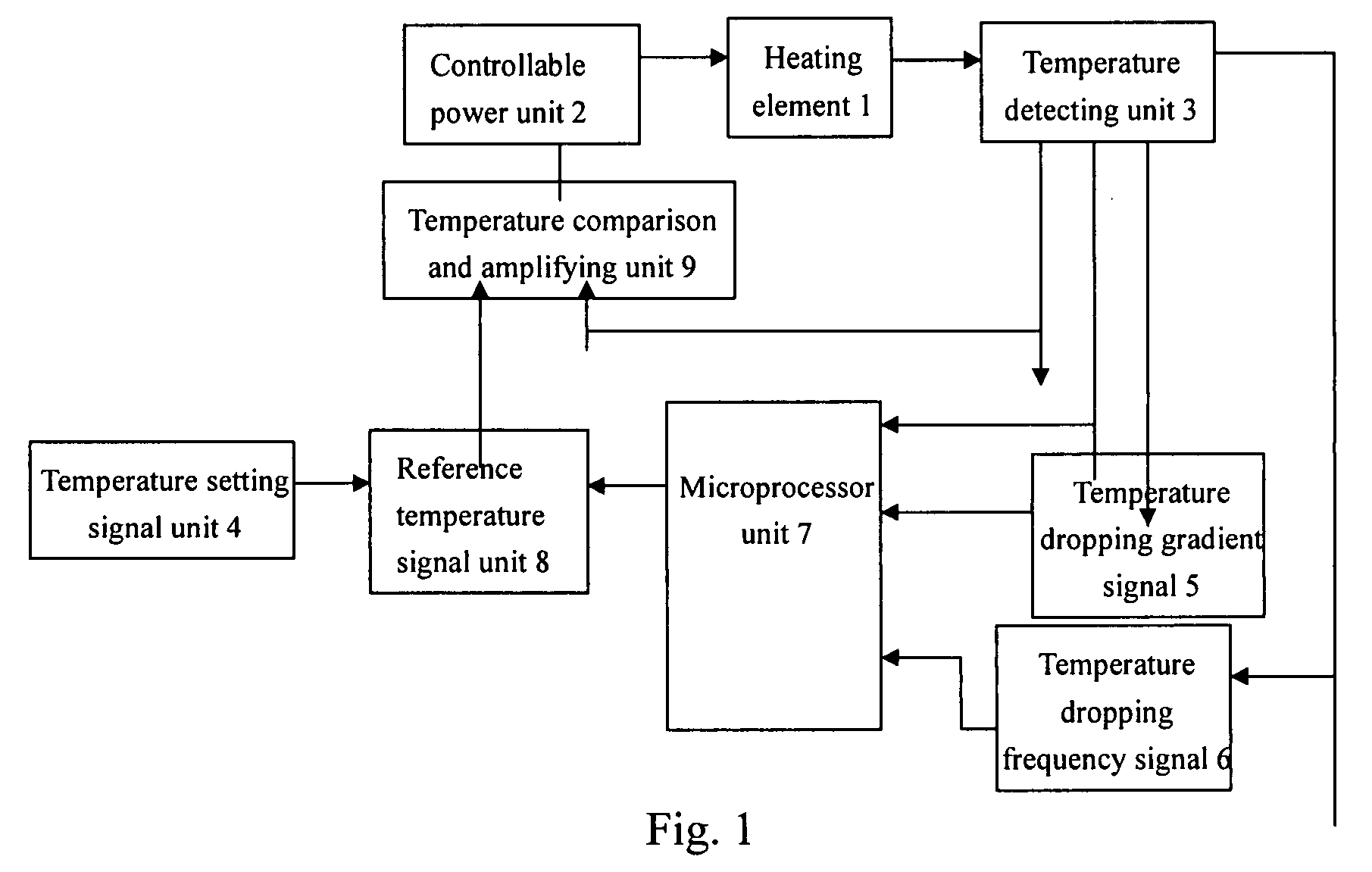
[0003]One aspect of the present invention is to provide a method and apparatus for power control of the heating element in the electric heating devices, which can rapidly detect change of temperature of the electric soldering iron or such other electric heating devices and rapidly adjust the power of the electric heating elements based on the change of temperature, to insure that the electric heating elements may work at a substantially constant temperature.
[0029]The method and apparatus for controlling temperature of heating element in accordance with the present invention may be applied to the electric soldering iron or such other electric heating devices, to efficiently and rapidly control the electric power of the heating element based on the temperature change of the heater of the heating element, insuring that in operation, the temperature of the heating element such as iron core of the electric soldering iron keeps at a setting temperature, which is adjustable according to the requirement, no matter how temperature of the heat load and temperature of the environment change. Therefore the method and apparatus in accordance with the present invention can save electric power, prolong life time of the electric heating element, and can also be applied to other cases where high electric heating temperature is demanded and electric heat load has variation.

Problems solved by technology

Electric heating elements are used more and more widely, and the conventional methods for temperature-power control of the electric heating elements usually utilize absolute temperature control manner, that is, these methods only sample and control the absolute temperature of the heating element, but cannot determine the work status of the heating element and the thermal requirement of the heated object and its effect to the temperature.
When the temperature is falling, the transient response of the heating element is poor, thus the re-rising of the temperature is slow, and this cannot be used in the case that the heat transfer of the heating element changes rapidly.
For example, temperature of the electric soldering iron is very high when it does not touch the metal to be welded, once it touches a big-size metal object or keeps contacting with the metal object for a long period of time, temperature of the electric soldering iron may fall rapidly due to the fast heat transfer, especially in the case that the metal to be welded has a large surface or the environmental temperature is low.
The conventional temperature control technologies for the electric soldering iron only consider the absolute temperature of the welding head, therefore the adjusting speed is slow, the power adjust cannot catch up with the variation of temperature, and the change of the power adjustment cannot catch up with the change of the temperature, even in some particular situations, the welding requirements cannot be satisfied because of the control delay.

Method used


Image

  • Temperature controlling device of heating element and method thereof
  • Temperature controlling device of heating element and method thereof

Examples


first embodiment

[0032]the controlling method in accordance with the present invention is as below:[0033]1. Setting an ideal temperature of the heated object (referred as given temperature) T0;[0034]2. Detecting a actual temperature T(t) of a heater of the heating element;[0035]3. Calculating a temperature dropping gradient dT / dt;[0036]4. Calculating a temperature dropping frequency d2T / dt2;[0037]5. Calculating a first temperature adjusting value DT1 based on a difference between the actual temperature and the set temperature, i.e. DT1=T(t)−T0;[0038]6. Calculating a second temperature adjusting value DT2 based on the temperature dropping gradient of the heating element, i.e. DT2=f(dT / dt);[0039]7. Calculating a third temperature adjusting value DT3 based on the temperature dropping frequency of the heating element, i.e. DT3=f(d2T / dt2);[0040]8. Calculating a total temperature adjusting value DT=DT1+DT2+DT3;[0041]9. Determining input power of the heating element, i.e. operating voltage supplied to the ...

second embodiment

[0043]In the step 7, determination of the third temperature adjusting value based on the temperature dropping frequency of the heating element can also be achieved through looking up a preset relation function table. The above steps 5-7 can also be combined to form a second embodiment as below:[0044]1. Setting a ideal temperature of the heated object (referred as given temperature) T0;[0045]2. Detecting a actual temperature T(t) of the heater of the heating element;[0046]3. Calculating a temperature dropping gradient dT / dt;[0047]4. Calculating a temperature dropping frequency d2T / dt2;[0048]5. Calculating a total temperature adjusting value DT through looking up a table based on the actual temperature T(t), the temperature dropping gradient dT / dt and the temperature dropping frequency d2T / dt2, i.e. DT=f(T(t), dT / dt, d2T / dt2);[0049]6. Determining input power of the heating element, i.e. operating voltage supplied to the heating element by the switching power supply, based on the total...


PUM

PropertyMeasurementUnit
temperatureaaaaaaaaaa
electric poweraaaaaaaaaa
frequencyaaaaaaaaaa

Abstract

A kind of temperature controlling device of heating element and method thereof detect the actual temperature of heating body of the heating element, and calculate the descending gradient and frequency of temperature based on the detected actual temperature. The norm signal is formed based on the actual temperature, descending gradient and frequency of the temperature to control the switch power as to achieve the split second control for the electric power of the heating element.

Description

FIELD OF THE INVENTION[0001]The present invention relates to temperature control technologies for the heating elements, more particularly, to a method and apparatus for power control of the heating element in the electric heating device such as electric soldering iron based on temperature.BACKGROUND OF THE INVENTION[0002]Electric heating elements are used more and more widely, and the conventional methods for temperature-power control of the electric heating elements usually utilize absolute temperature control manner, that is, these methods only sample and control the absolute temperature of the heating element, but cannot determine the work status of the heating element and the thermal requirement of the heated object and its effect to the temperature. When the temperature is falling, the transient response of the heating element is poor, thus the re-rising of the temperature is slow, and this cannot be used in the case that the heat transfer of the heating element changes rapidly...

Claims


Application Information

Patent Timeline
Patent Type & Authority Applications(United States)
IPC IPC(8): G05D23/00H05B1/02
CPCG05D23/19
Inventor LIU, XIAOGANG
Owner L LAB
Learn More