Compression Post Mount

a compression post and mounting technology, applied in the field of fences and guard rails, can solve the problems of similar difficulties, hole drilling, unsightly and bulky, etc., and achieve the effects of reducing concrete spalling or cracking, superior structural strength, and reducing drilling

a compression post and mounting technology, applied in the field of fences and guard rails, can solve the problems of similar difficulties, hole drilling, unsightly and bulky, etc., and achieve the effects of reducing concrete spalling or cracking, superior structural strength, and reducing drilling

US20090183354A1Inactive Publication Date: 2009-07-23HOMELAND VINYL PRODS

Image

  • Compression Post Mount
  • Compression Post Mount
  • Compression Post Mount

Examples


Embodiment Construction

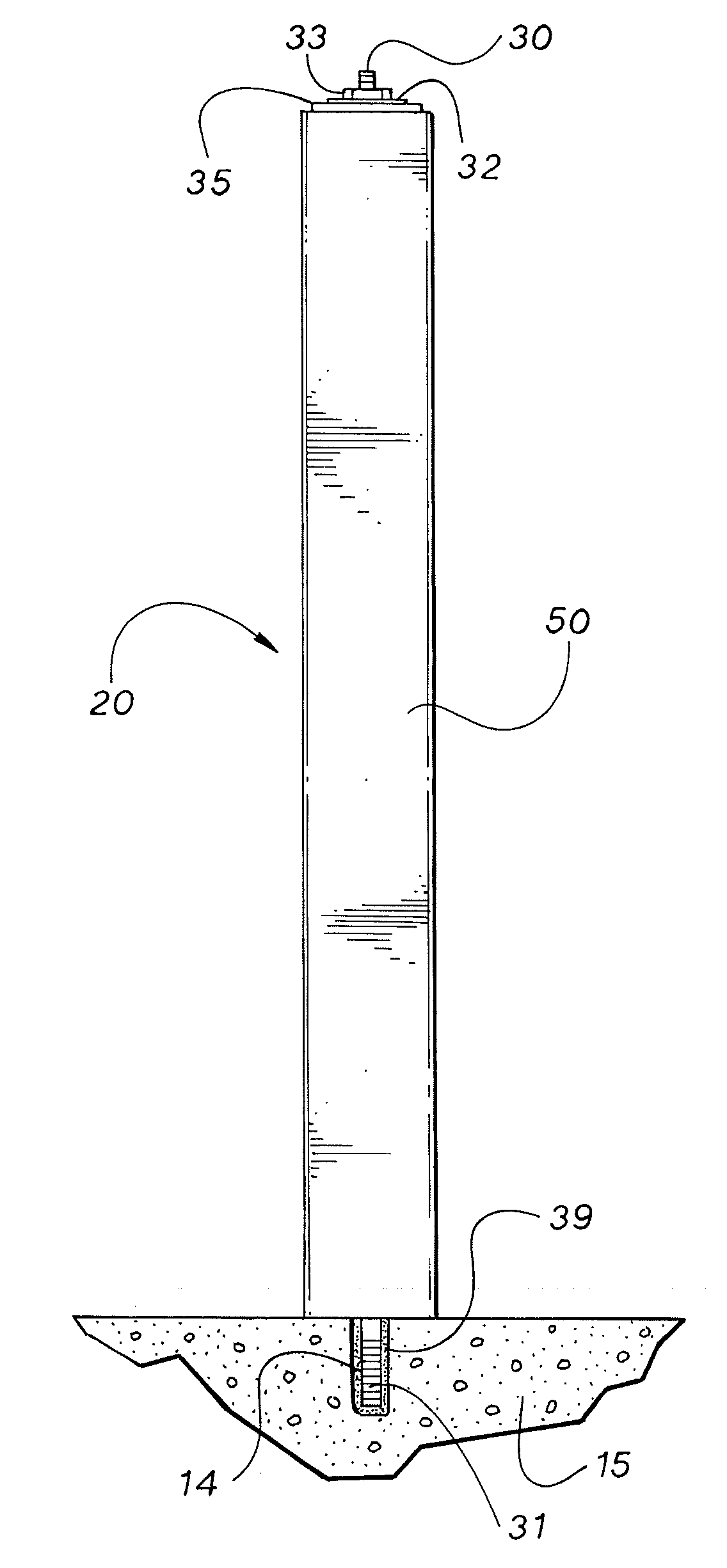
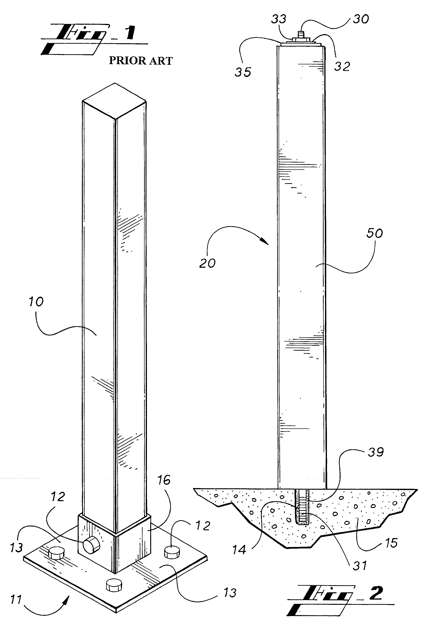
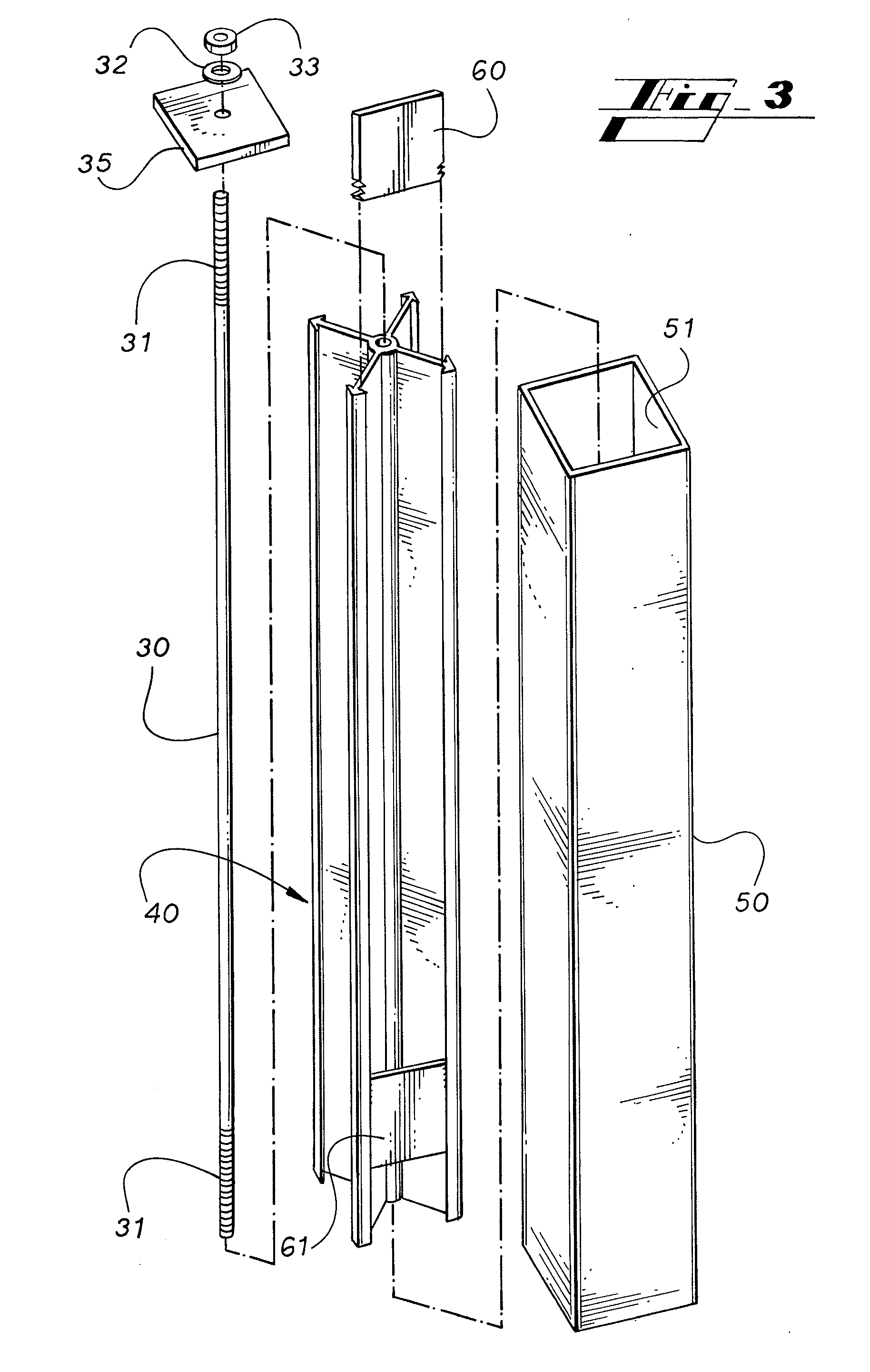
[0021]FIG. 1 depicts a fence post 10 mounted by a typical mounting bracket 11 found in the prior art. As may be seen the post mount in the prior art requires a plurality of fasteners 12 and the base plate 13 exceeds the outer periphery of the post 10. By comparison with the post support 20 of the present invention depicted in FIGS. 2 and 3, the unsightly base bracket 11 and the requirement to drill a plurality of holes in the underlying substructure is eliminated. The post assembly 20 contemplated by the present invention includes an attachment rod 30, an internal support member 40, a sleeve 50, and an optional mounting adapter plate 60.

[0022]As seen in reference to FIG. 2, a single hole 14 is all that is required to mount the post assembly 20 in the underlying substructure 15. As depicted in FIG. 2, the substructure 15 is concrete. The single hole 14 is drilled to a suitable depth, preferably to a depth of at least 4 inches. For a one-half inch attachment rod we have found that a ⅝...


PUM

PropertyMeasurementUnit
depthaaaaaaaaaa
adhesiveaaaaaaaaaa
longitudinal lengthaaaaaaaaaa

Abstract

A fence post assembly for mounting to a substructure with a single point of attachment. The post assembly has an outer sleeve surrounding a support member and an attachment rod extending through the support member. The post assembly is mounted to the substructure by securing one end of the attachment rod in the substructure and securing the support member between a compression plate and the substructure by tensioning the upper end of the attachment rod. Attachment points for securing additional fence components to the post are provided by inserting an adapter into a receiving channel defined along a longitudinal length of the support member.

Description

RELATED APPLICATION[0001]This divisional application claims the benefit of U.S. patent application Ser. No. 11 / 668,219, filed Jan. 29, 2007 and is incorporated by reference.FIELD OF THE INVENTION[0002]The present invention relates generally to the field of fences and guard rails. More particularly, the invention relates to support posts for fences and guard rails. With even greater particularity, the invention relates to a method of assembling and components for mounting a support post to a structure without external bracing.BACKGROUND OF THE INVENTION[0003]In the art of fences numerous materials and methods have been employed to construct and design fences for various purposes such as containment of livestock, pets, people and the like or for the exclusion of the same. In other instances, fences may be employed to add a decorative or aesthetic flourish to structures and landscapes.[0004]More recently, vinyl, plastics and similar such materials have been found to be advantageous for...

Claims


Application Information

Patent Timeline
23 Jul 2009
Publication
US20090183354A1
IPC
B23P11/00
CPC
E04H12/2253; Y10T29/49885; Y10T29/49826; Y10T29/49881; Y10T29/49631
Inventors
MCGINNESS, WILLIAM G.; HEATH, RANDALL