Exhaust emission control device

a technology of exhaust emission control and control device, which is applied in the direction of exhaust treatment electric control, machines/engines, mechanical equipment, etc., can solve the problems of deteriorating the purification performance of the catalytic converter

Inactive Publication Date: 2009-07-23
CALSONIC KANSEI CORP
View PDF10 Cites 15 Cited by
  • Summary
  • Abstract
  • Description
  • Claims
  • Application Information

AI Technical Summary

Benefits of technology

[0008]According to a first aspect of the present invention there is provided an exhaust emission control device including an adsorbent trapper, a catalytic converter, a main exhaust gas passage, a first valve, a bypass exhaust gas passage, a second valve and a control unit. The adsorbent trapper has an adsorbent that can adsorb hydrocarbon in exhaust gas discharged from an internal combustion engine on the adsorbent a low temperature thereof and desorb the hydrocarbon from the adsorbent at a high temperature thereof. The catalytic converter is arranged at a downstream side of the adsorbent trapper and has catalyst for purifying the exhaust gas. The main exhaust gas passage is arranged between the internal combustion engine and the catalytic converter so that the main exhaust passage can flow the exhaust gas discharged from the internal combustion engine to the catalytic converter. The first valve is arranged in the main exhaust gas passage and it is capable of opening and closing to flow the exhaust gas through the main exhaust gas passage and shut the main exhaust gas passage. The bypass exhaust gas passage has an upstream portion connected with an upstream portion of the main exhaust gas passage to bypass the first valve and have the adsorbent trapper in the bypass exhaust gas trapper. The second valve is arranged in the bypass exhaust gas passage and it is capable of opening and closing to flow the exhaust gas through the bypass exhaust gas passage and shut the bypass exhaust gas passage. The control unit controls the first valve and the second valve to open so that the exhaust gas flow through the main exhaust gas passage and the bypass exhaust gas passage so as to desorb the hydrocarbon from the adsorbent when a condition is satisfied, where the condition is that the catalyst converter is in active, an oxygen adsorption amount of the catalyst converter is not less than a first predetermined amount and an exhaust gas amount is not more than a second predetermined amount, while the control unit controls the first valve to open and the second valve to close when the condition is not satisfied during desorption of the hydrocarbon from the adsorbent.
[0009]According to a second aspect of the present invention there is provided an exhaus...

Problems solved by technology

However, in the above known conventional exhaust emission control device, there are a problem in that the purification performance of the catalytic converter is deteriorated due to lack of the oxygen adsorption amount of the catalytic converter bec...

Method used


Image

  • Exhaust emission control device
  • Exhaust emission control device
  • Exhaust emission control device

Examples


first embodiment

[0044]The operation and effects of the exhaust emission control device 1 of the first embodiment will be described.

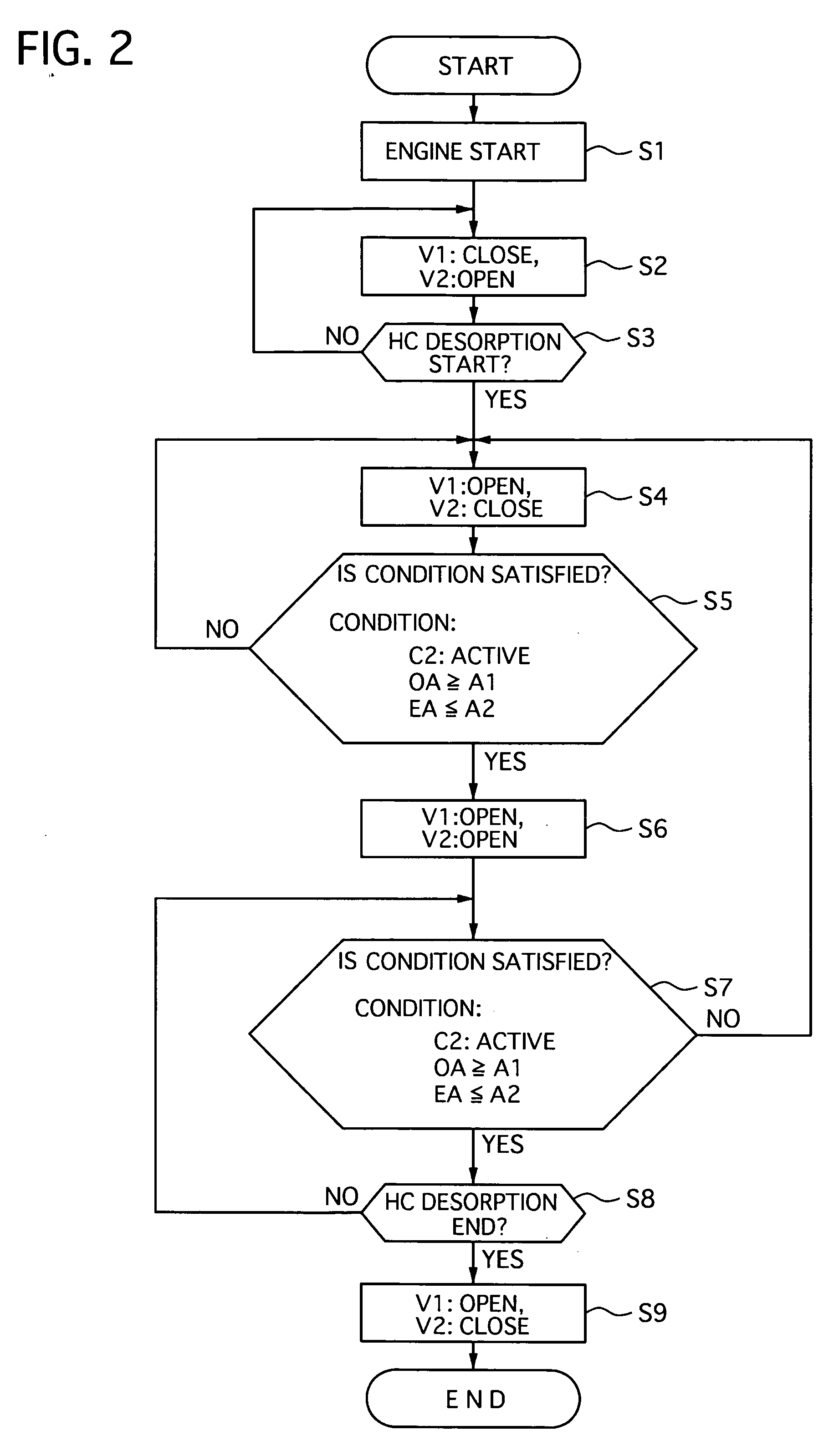
[0045]In the exhaust emission control device 1 of the first embodiment, the engine control unit 8 controls the first valve V1 and the second valve V2 to open and close according to a flowchart shown in FIG. 2 of valve open / close control executed by the engine control unit 8.

[0046]At step S1, the engine control unit 8 starts the open / close control when it detects a start of the engine 1, and then the flow goes to step S2.

[0047]At the step S2, the first valve V1 is closed to shut the main exhaust passage 4, the second valve V2 being opened to flow the full amount of the exhaust gas discharged from the engine 2 through the bypass exhaust gas passage 5, and then flow goes to step S3.

[0048]At the step S3, the engine control unit 8 judges whether or not the adsorbent in the adsorbent trapper 6 begins to desorb the exhaust gas therefrom based on the temperature signal outputte...

second embodiment

[0082]In addition, although the NOx amount in the exhaust gas increases only in a case where the engine 2 is driven merely at the lean mixture, the exhaust emission control device 1 of the second embodiment uses the lean mixture control with the fuel injection cut-off, so that the oxygen can be supplied to the second catalytic converter C2 without increase in NOx because the air fuel ratio is not changed.

[0083]FIG. 7 shows experiment results, of a conventional exhaust emission device and that of the second embodiment, showing a relationship between the amount of HC emission, a vehicle speed and an elapsed time since the engine 2 is started. The vehicle speed is set according to a speed model that is used for experiments. The conventional exhaust emission control device is constructed in such a way that a first valve V1 and a second valve V2 are opened to flow the exhaust gas through the main exhaust gas passage 4 and the bypass exhaust gas passage 5 immediately after a second cataly...

third embodiment

[0085]Next, an exhaust emission control device of a third embodiment according to the present invention will be described with the accompanying drawings.

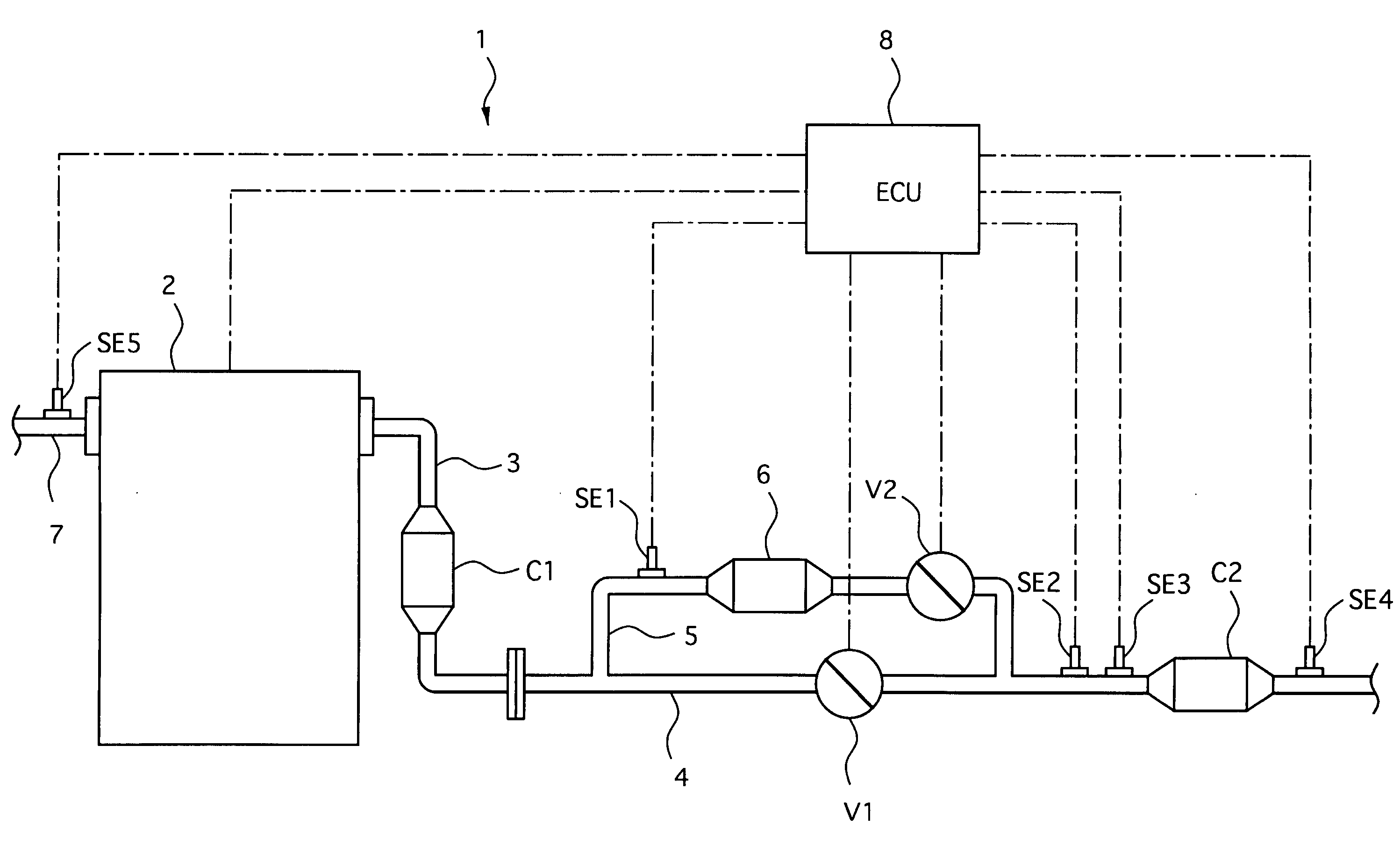
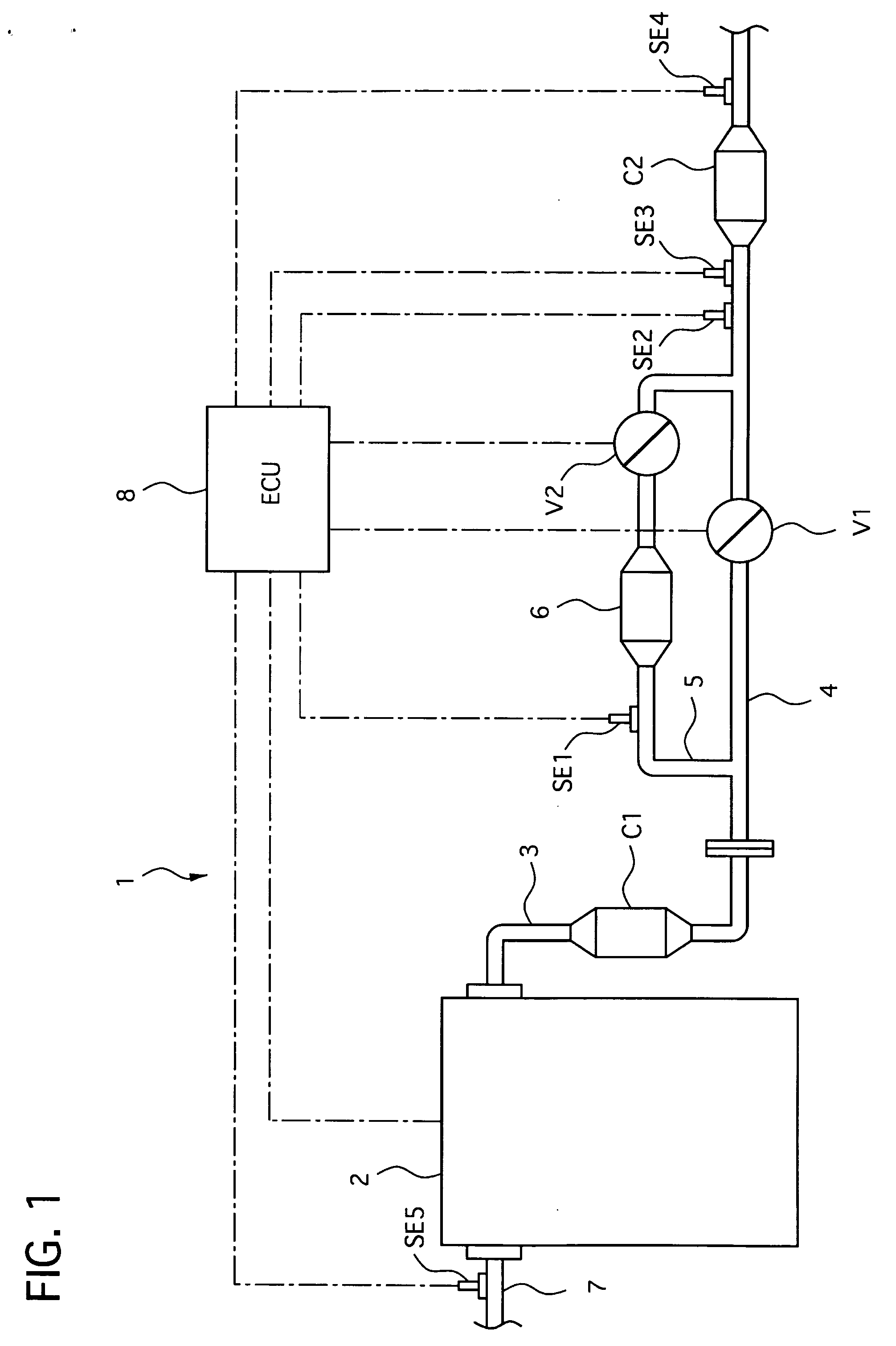
[0086]As shown in FIG. 8, the exhaust emission control device 11 includes a first catalytic converter C1, a main exhaust gas passage 4, a bypass exhaust gas passage 5, a second catalytic converter C2 with an adsorbent trapper, a first valve V1, a second valve V2, a center muffler MF, a rear muffler MR and an emission control unit 12. The emission control unit corresponds to the control unit of the present invention.

[0087]The first catalytic converter C1 is constructed similarly to that of the first embodiment, and is connected with an engine 2 at its upstream portion through an exhaust manifold 3 and with a connecting pipe 3a at its downstream portion.

[0088]A downstream side end portion of the connecting pipe 3a is provided with a flange that is joined with a flange 25 of an upstream side end portion of the main exhaust gas passage ...


PUM


Abstract

An exhaust emission control device includes an adsorbent trapper having an adsorbent for adsorbing and desorbing hydrocarbon in exhaust gas, a catalytic converter, a main exhaust gas passage with a first valve, a bypass exhaust gas passage with a second valve and a control unit. The bypass exhaust gas passage bypassing the first valve is connected with the adsorbent. The control unit controls the first and second valves to desorb the hydrocarbon from the adsorbent when a condition is satisfied. The condition is that the catalyst converter is in active, an oxygen adsorption amount of the catalyst converter is not less than a first predetermined amount and an exhaust gas amount is not more than a second predetermined amount. The first valve is opened and the second valve is closed when the condition is not satisfied during desorption of the hydrocarbon from the adsorbent.

Description

BACKGROUND OF THE INVENTION[0001]1. Field of the Invention[0002]The present invention relates to an exhaust emission control device that controls exhaust emission discharged from an internal combustion engine.[0003]2. Description of the Related Art[0004]A conventional exhaust emission control device of this kind is disclosed in Japanese Patent Application Laid-Open Publication NO. 06-229235. This conventional exhaust emission control device has a main exhaust gas passage and a bypass exhaust gas passage that are arranged in parallel to each other at an upstream side of an exhaust emission control catalytic converter. The bypass exhaust gas passage is provided with an adsorbent that can adsorb hydrocarbon (HC) contained in an exhaust gas at a low temperature and desorb the HC adsorbed thereon at a high temperature. The conventional exhaust emission control device further has a valve for opening and closing the bypass exhaust gas passage. The valve is controlled by a control unit acco...

Claims


Application Information

Patent Timeline
IPC IPC(8): F01N9/00
CPCF01N3/0835F01N3/0878F01N2240/18F01N13/009F01N2570/12Y02T10/20F01N2550/03Y02T10/12
Inventor UCHIDA, KAZUYANISHIZAWA, KIMIYOSHIOOUCHI, KENBAN, KUNIKAZU
Owner CALSONIC KANSEI CORP
Why Eureka
Try Eureka