Low Voltage Drop Unidirectional Electronic Valve

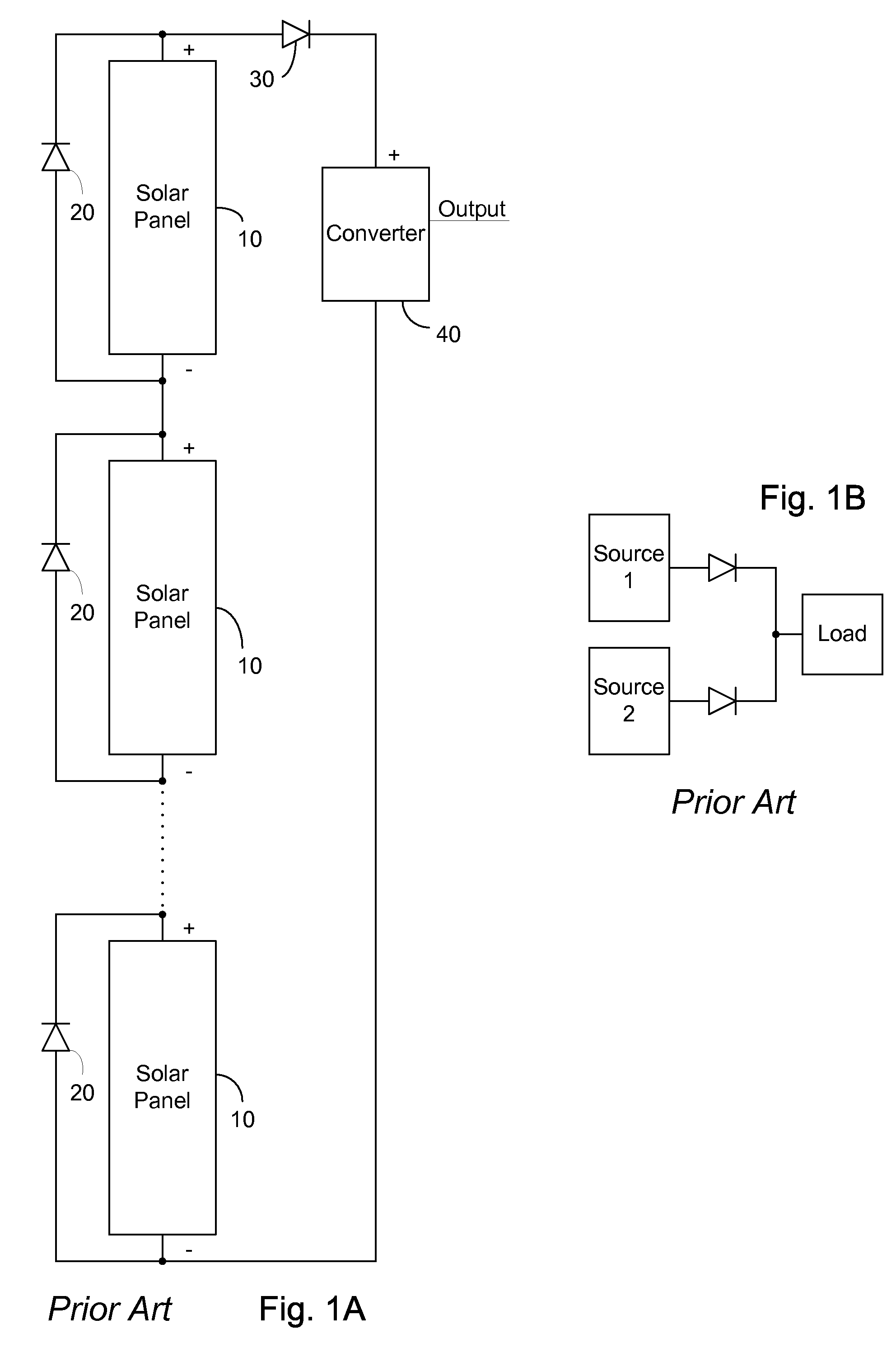
a technology of electronic valves and low voltage drop, which is applied in the direction of pulse techniques, electronic switching, transistors, etc., can solve the problems of power loss, loss of system, and ultimately cost of arrangement of fig. 1a

Inactive Publication Date: 2009-07-23
MICROSEMI CORP ANALOG MIXED SIGNAL GRP LTD
View PDF9 Cites 181 Cited by
  • Summary
  • Abstract
  • Description
  • Claims
  • Application Information

AI Technical Summary

Benefits of technology

[0009]Accordingly, it is a principal object of the present invention to overcome the disadvantages of prior art unidirectional electronic valves. This is provided in certain embodiments by an electronically controlled switch comprising a pair of reverse serially connected field effect transistors arranged to block current flow when the electronically controlled switch is open and unidirectionally pass current when the electronically controlled switch is closed responsive to a control circuit. Power for the switch and the control circuit is taken from a voltage reversal, and held by a capacitor. Preferably, the electronically controlled switch comprises a pair of field effect transistors (FETs), further preferably metal oxide silicon FETs (MOSFETs), further preferably n-channel MOSFETS, connected so that their internal body diodes do not present a through path for electricity in either direction between the return terminal and positive terminal. The pair of MOSFETS, in cooperation with the control circuit, represents a near ideal diode.

Problems solved by technology

The power lost to the system is emitted as heat, which thus drives thermal considerations for panel layout, construction of bypass diode 20 and ultimately cost of the arrangement of FIG. 1A.
The power supply exhibiting the larger voltage potential will drive the single load however power is lost due to the voltage drop across the ORing diode.

Method used


Image

  • Low Voltage Drop Unidirectional Electronic Valve
  • Low Voltage Drop Unidirectional Electronic Valve
  • Low Voltage Drop Unidirectional Electronic Valve

Examples


Embodiment Construction

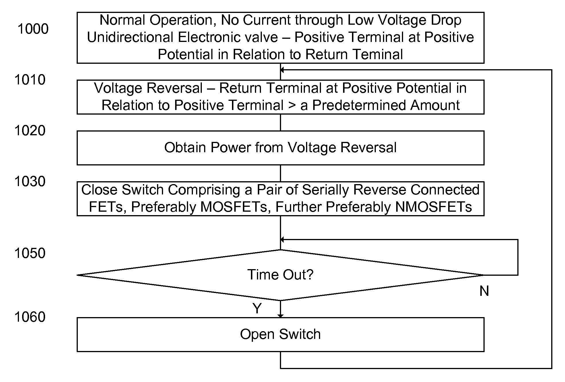
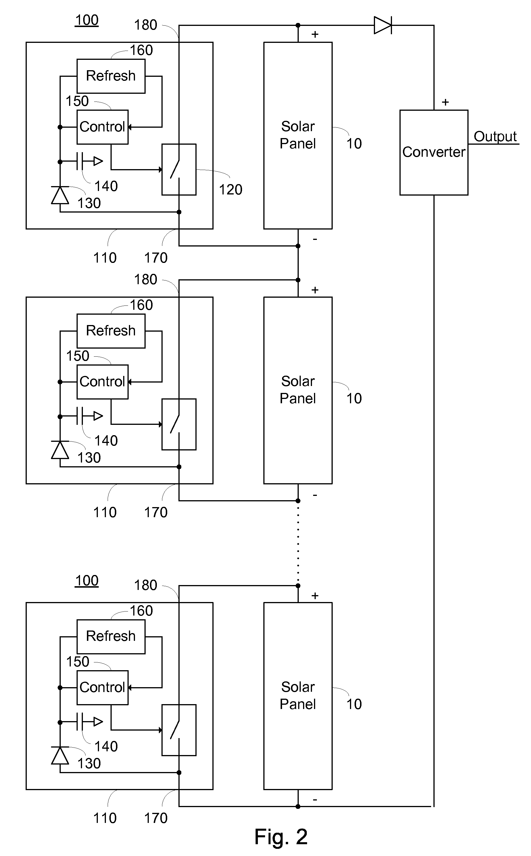
[0022]The present embodiments enable a low voltage drop unidirectional electronic valve comprising a pair of reverse serially connected field effect transistors arranged to block current flow when the electronically controlled switch is open and unidirectionally pass current when the electronically controlled switch is closed. Periodically, the electronically controlled switch is opened thereby refreshing the circuit.

[0023]Before explaining at least one embodiment of the invention in detail, it is to be understood that the invention is not limited in its application to the details of construction and the arrangement of the components set forth in the following description or illustrated in the drawings. The invention is applicable to other embodiments or of being practiced or carried out in various ways. Also, it is to be understood that the phraseology and terminology employed herein is for the purpose of description and should not be regarded as limiting.

[0024]FIG. 2 illustrates a...


PUM


Abstract

A low voltage drop unidirectional electronic valve constituted of: a first terminal; a second terminal; an electronically controlled switch arranged to allow the flow of current from the first terminal to the second terminal when closed, the electronically controlled switch comprising a pair of reverse serially connected field effect transistors; a control circuit, arranged to close the electronically controlled switch responsive to the potential of the first terminal exceeding the potential of the second terminal by a predetermined amount; and a refresh circuit arranged to periodically open the electronically controlled switch. In one embodiment the low voltage drop unidirectional valve is arranged as one of a solar bypass element and an ORing diode.

Description

CROSS-REFERENCE TO RELATED APPLICATIONS[0001]This application claims priority from U.S. Provisional Patent Application Ser. No. 61 / 022,515 filed Jan. 22, 2008, of the same title, the entire contents of which are incorporated herein by reference.BACKGROUND[0002]The invention relates generally to the field of unidirectional electronic valves, and more particularly to a low voltage drop unidirectional electronic valve operating as a near ideal diode.[0003]Solar power for large scale use, and / or for feeding into a power grid, is typically supplied by an array of serially connected solar panels. Each solar panel exhibits a positive terminal, and a return, or negative terminal. Solar panels generate electricity in the presence of an appropriate amount of sunlight, and thus one solar panel in the array may be in a dark condition, while others may be generating electricity. The dark condition may be caused by, among others, a flying object or bird, a cloud covering, or accumulated dirt. Ele...

Claims


Application Information

Patent Timeline
Patent Type & Authority Applications(United States)
IPC IPC(8): H03K17/687
CPCH01L31/02021Y02E10/50H03K17/74H03K17/063
Inventor FAHRENBRUCH, SHAWN ANTHONY
Owner MICROSEMI CORP ANALOG MIXED SIGNAL GRP LTD
Why Eureka
Try Eureka