
Space diversity optical receiver and system and method using the same

Inactive Publication Date: 2009-07-23
CELIGHT
View PDF12 Cites 19 Cited by
  • Summary
  • Abstract
  • Description
  • Claims
  • Application Information

AI Technical Summary

Benefits of technology

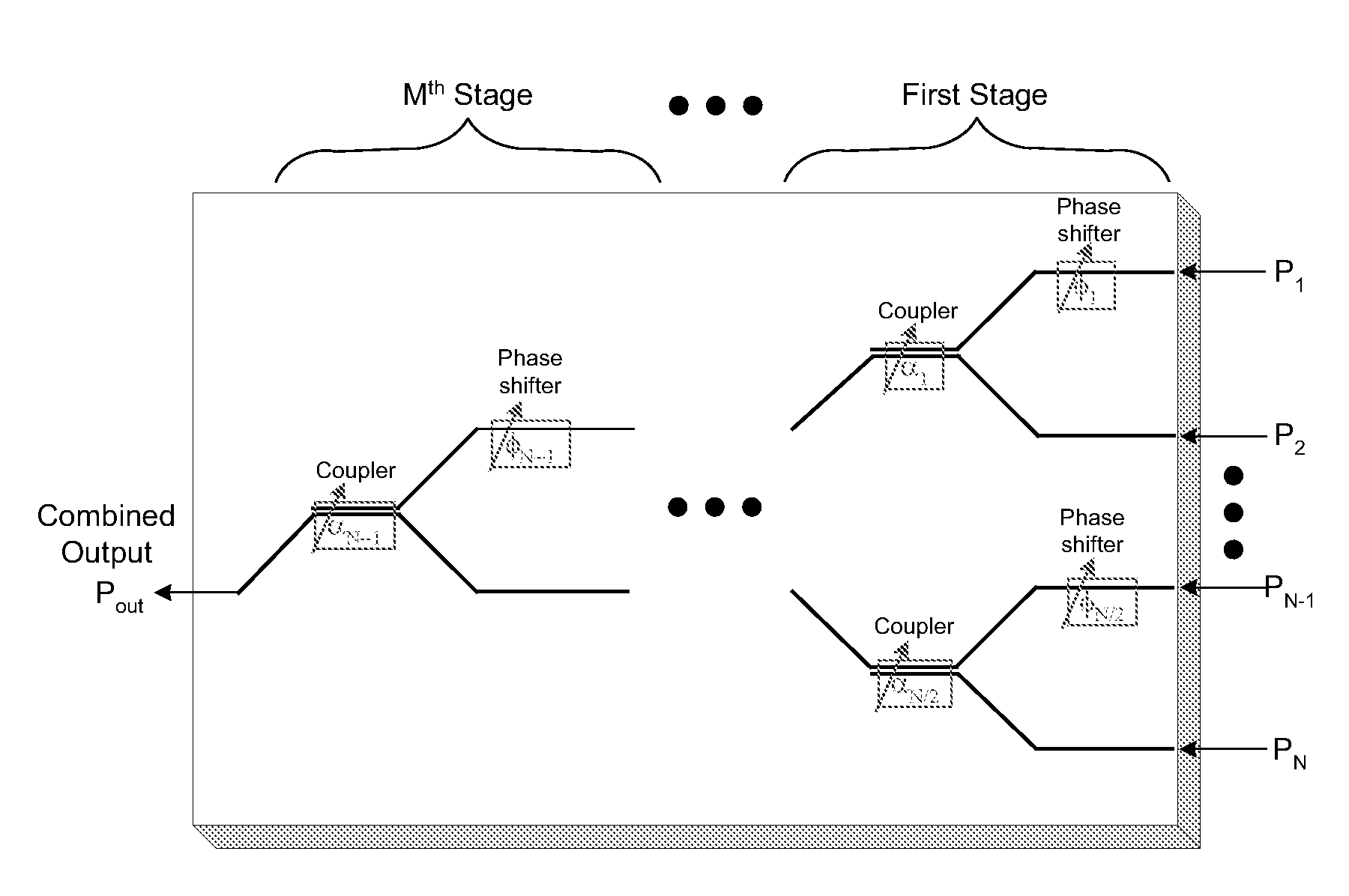
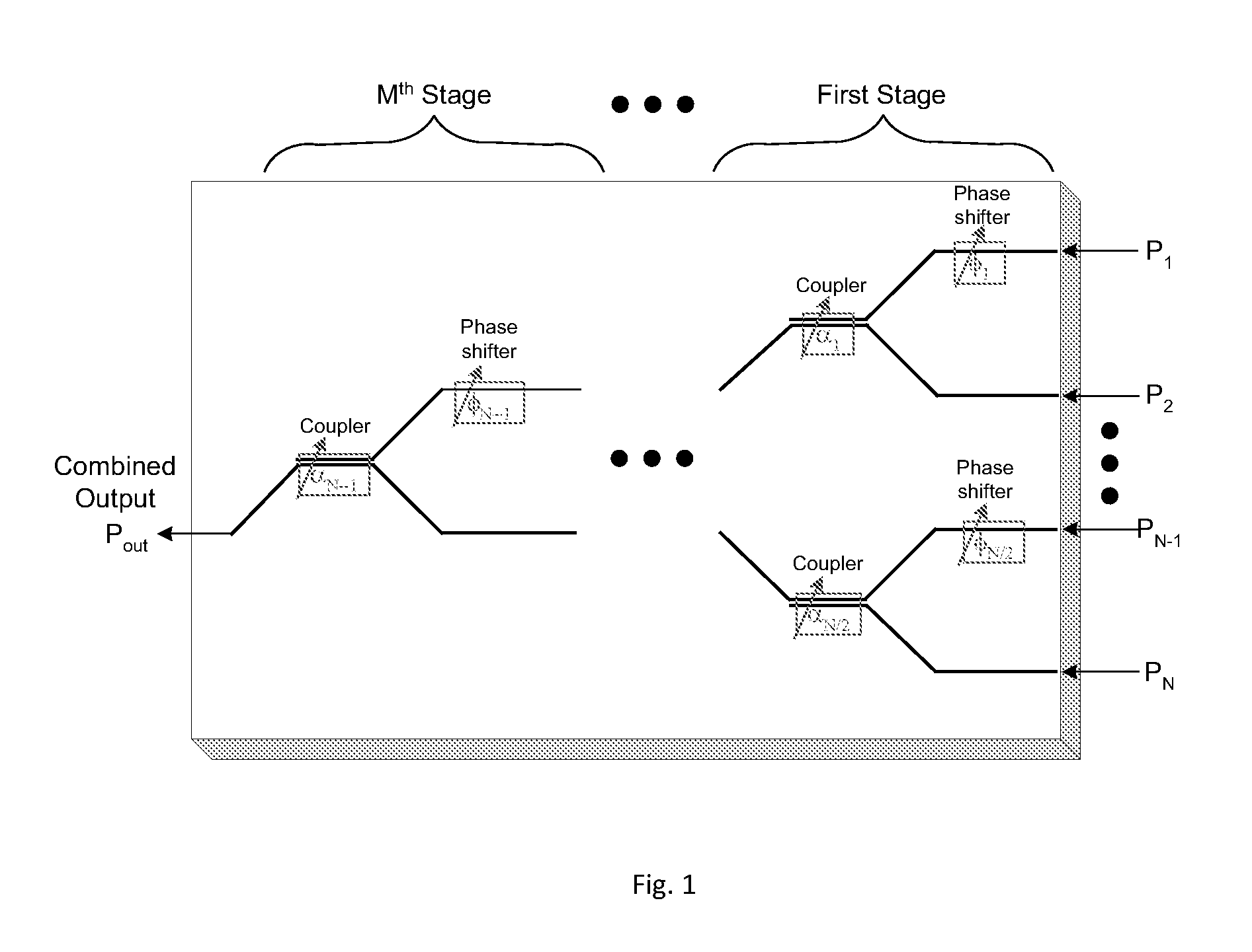
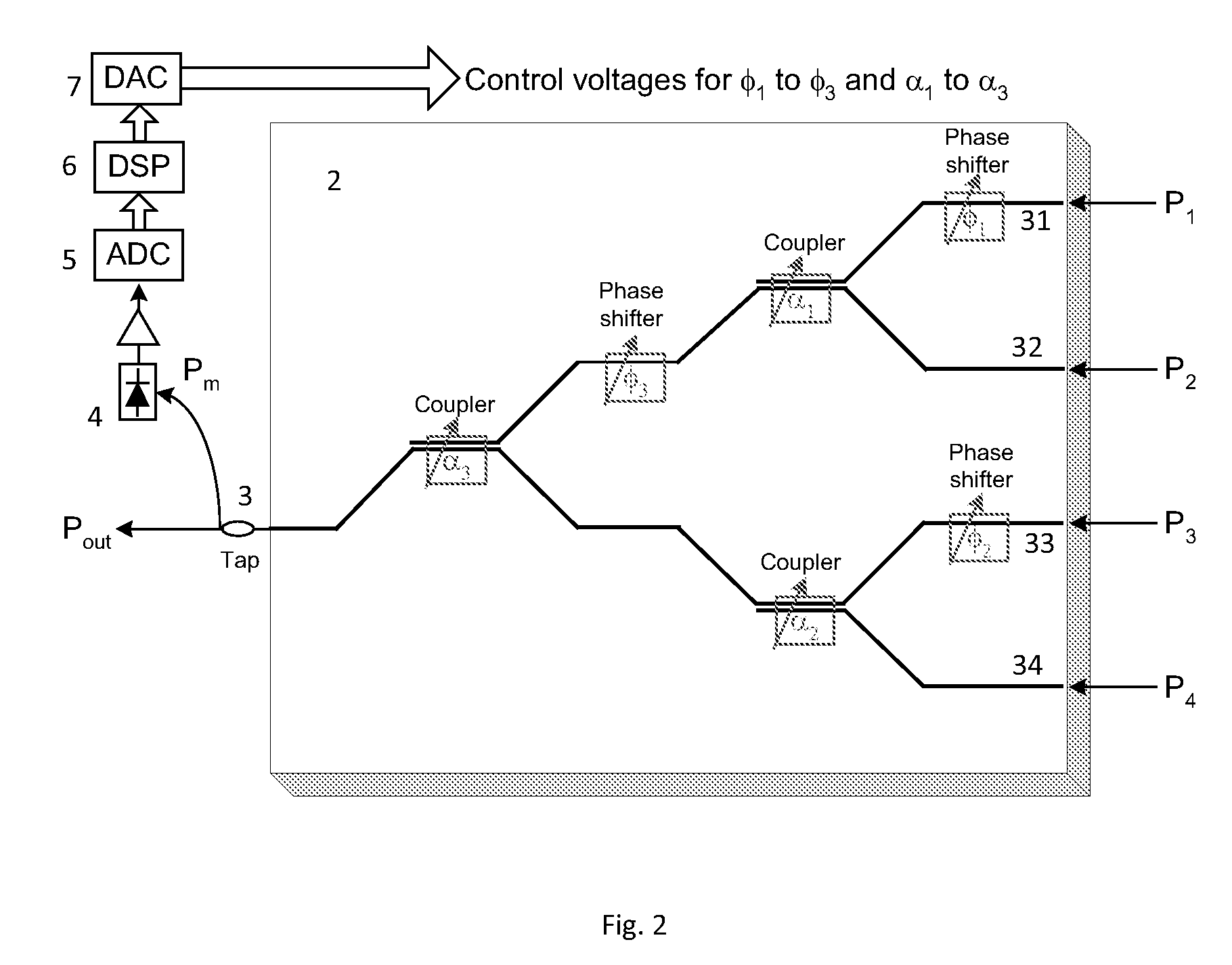
[0006]Accordingly, an object of the present invention is to provide an electro-optically adjustable optical beam combining device that can track and compensate for the phase and amplitude distortion across the optical beam caused by the turbulence thereby producing a final single-mode output beam with a maximum optical power. Such an optical device has 2M input waveguides (M is an integer≧1), each receiving a portion of the incoming optical beam. The waveguides are connected by (2M−1) directional couplers forming a tree-like structure; each coupler is formed by two waveguides, coming in and out of the coupler. In the preferred embodiment, the directional coupler is a two-section coupler with an alternating or reversed Δβ. Δβ is the mismatch of the propagation constants of the two coupling waveguides that form the directional coupler. In each coupler one of the two input waveguides has a phase shifter for changing an input phase of the optical beam portion in the same waveguide before its coupling. Furthermore, the power coupling ratio of each (2M−1) directional couplers can be adaptively adjusted in respond to the optical beams in the two input waveguides. The output waveguide forms an input waveguide for a subsequent coupler from (2M−1) couplers. A final output waveguide from the last coupler is a final output beam of the device. The control means operate to change the phases of the beams propagating in the waveguides before their coupling as well as to change the coupling ratio of the coupler. This change aims to maximize the final output beam power. The control means may include a photodetector receiving a beam in the final output waveguide, producing an electrical signal proportional to the output optical power. The coupling ratio of the coupler as well as the input phase of the optical beam portion in the same waveguide before its coupling is adjusted in a manner that maximizes the output optical power in the final output waveguide. The input phase is changed in a phase shifter connected to the same waveguide before coupling. The coupling ratio is changed in the coupler itself.

Problems solved by technology

The atmospheric turbulence effect on an optical beam, noticeable as beam drift, spread, and scintillation, is the main source of impairments in the free-space optical communications.
It leads to the decreased link capacity, bit-error-rate deterioration and sometimes unavailability of the transmission or fading.
In the presence of the strong phase and intensity fluctuations characteristic of near-earth propagation paths, these types of systems tend to perform poorly.
Furthermore, such systems cannot compensate for fast phase change; their operation speed is limited by the hardware response as well as data processing time.

Method used


Image

  • Space diversity optical receiver and system and method using the same
  • Space diversity optical receiver and system and method using the same
  • Space diversity optical receiver and system and method using the same

Examples


Embodiment Construction

[0018]The present invention now will be described more fully hereinafter with reference to the accompanying drawings, in which the preferred embodiments of the invention are shown. This invention may, however, be embodied in many different forms and should not be construed as limited to the embodiments set forth herein; rather, these embodiments are provided so that this disclosure will be thorough and complete, and will fully convey the scope of the invention to those skilled in the art.

[0019]Optical signal transmission in free space is susceptible to atmospheric-induced attenuation and scattering. At the receiver side the beam must be collected and focused on the photodetector. However, the spatial distribution of the optical phase and amplitude is not uniform across the beam caused by turbulence in the atmosphere. As a result, the amount of optical power that can be focused into a small aperture of a photodetector is significantly reduced. The optical power also fluctuates due to...


PUM


Abstract

An optical beam combiner is provided, which allows efficient collection of light for various applications: non-line of sight and free space optical communications, remote sensing, optical imaging and others. A multitude of optical beam portions is captured by a space diversity receiver that includes an optical beam combiner, which has a tree-like topology with interconnected waveguides, electro-optic phase shifters, and directional couplers. For each of the beam portions the phase of the phase shifter and the coupling ratio of coupler in the optical beam combiner are tuned sequentially to maximize the final output power in the final optical waveguide. A portion of the final output beam is used for the power detection and forming a feedback signal for the phases and coupling ratios adjustment. The data or information is recovered from the received final optical beam using coherent detection.

Description

CROSS-REFERENCE TO RELATED APPLICATIONS[0001]This application claims priority of provisional Application Ser. No. 61 / 090,404 filed Aug. 20, 2008. It is also a continuation-in-part of U.S. patent application Ser. No. 11 / 695,920 filed Apr. 3, 2007, Ser. No. 10 / 669,130 filed Sep. 22, 2003, Ser. No. 11 / 610,964 filed Dec. 14, 2006; Ser. No. 11 / 672,372 filed Feb. 7, 2007; Ser. No. 12 / 045,765 filed Mar. 11, 2008; Ser. No. 12 / 137,352 filed Aug. 15, 2008, Ser. No. 12 / 371,249 filed Feb. 13, 2009, all of which applications are fully incorporated herein by reference.FIELD OF THE INVENTION[0002]This invention relates generally to laser systems and methods of receiving at least a portion of the laser beam after its transmission through turbulent media such as the atmosphere or underwater. The system includes means for compensation of the optical phase and amplitude distortion as a result of turbulence-induced perturbations in the received beam. The applications comprise free-space optical communi...

Claims


Application Information

Patent Timeline
IPC IPC(8): H04B10/06G01J1/10G02B6/26
CPCH04B10/61
Inventor CHO, PAK SHINGKHURGIN, JACOBSHPANTZER, ISAAC
Owner CELIGHT
Learn More