Method and apparatus for powering of amphibious craft

a technology for amphibious craft and powering systems, applied in marine propulsion, electric generator control, vessel construction, etc., can solve the problems of limiting the usefulness and utility of jet drives within various types of marine vessels including amphibious craft, limiting the usefulness and utility of monitoring the true efficiency of jet drives within various types, and lagging efficiency control efficiency, so as to achieve fast control dynamics and control the effect of active motor braking control

Inactive Publication Date: 2009-07-23
SULLIVAN & COMPANY
View PDF1 Cites 56 Cited by
  • Summary
  • Abstract
  • Description
  • Claims
  • Application Information

AI Technical Summary

Benefits of technology

[0031]In some embodiments, Traction Control Systems (TCS) may be applied to the in wheel hub motor / generators to be actively controlled by the motor controller at anytime with extremely fast control dynamics. The motor controller may be used to influence any aspect of a vehicle's performance, including motoring, braking, steering and cornering. Control of wheel traction influences motoring, braking, steering and cornering accomplished by a comprehensive Traction Control System (TCS) system and requires sensors and control systems with complex control algorithms generated by controls systems engineers to design and program Traction Control System (TCS) computers within the intelligent motion controls of the vehicle desired behavior for any situation with the ability to apply advances in mathematics and intelligent controls taking advantage of the fast control dynamics available when incorporating in wheel hub motor / generators for the purpose of maneuvering and braking controls for a vehicle of any type that would benefit from such advantages in precision, accuracy and speed of control dynamics. Sensors on the vehicle will tell the TCS computer what the vehicle's behavior actually is at any point in time and the computer will then use mathematical models of the in wheel hub motor / generator and vehicle dynamics to determine what actions should be taken to make actual vehicle behavior most closely match desired vehicle behavior. Closed loop feedback can be used to fine tune any algorithms used while the vehicle is being operated. Such loop feedback may include feedforward to account for gradual disturbances such as changes in terrain influences and the mathematical in wheel hub motor / generator model is used to predict the required application of positive or negative torque, and electrical power required to produce a desired torque at each individual wheel. This model would include motor torque for any RPM, temperature, tire air pressure, loading, terrain etc. This torque can be negative (braking torque) or positive (motoring torque). The model would also include things like in wheel hub motor / generator rotational inertia, wheel drag, effective rolling radius, wheel slip, slip angle, steering, braking power, motoring power, vehicle velocity and angular position, and tire torsion stiffness. The mathematical vehicle dynamics model is needed to predict the wheel torque required to produce a desired behavior on the contact surface. Such a model would include the center of gravity (CG), torsion forces acting upon the CG, aerodynamic forces, masses, moments of inertia, tire information, and suspension positions and be able to predict the impact and affects of the changes in dynamics to the control capability and limits of system control capability. The vehicle dynamics model would be improved with variable contact surface mapping including bumps, hills, corners, turns, banks and other contact surface influences that cause changes in the contact patch geometry and the associated effects on vehicle behavior. The intention of the model is to develop dynamic expressions for control algorithms to be used later on for control purposes and to derive the coefficient of tire-road friction or coefficient of adhesion as a function of the vehicle dynamics. The models allow the Traction Control System (TCS) to alter the current behavior to desired behavior. Desired behavior is limited within the confines of a safe operation envelop. Control inputs from the operator operate within the envelop of safety confines that are defined by the control system rules and during normal braking input commands from the operator are such that regenerative braking is applied and during hard or emergency braking the vehicle will effectively have active motorized braking control. Regenerative braking controls are removed from the braking control system. Motorized braking is applied to the individual in wheel hub motor / generators such that a negative torque is applied to the individual wheels to provide for more effective braking power than regenerative braking could apply and if there is too much brake force applied to the in wheel hub motor / generator then the ABS can alter the applied torque to each individual such as to optimize the applied torque according to a defined slip value that maximizes the braking force while maintaining maximum steering control capability and the operator of the vehicle will have quicker braking capability and less concern of locking the wheels, for example locking of the rear wheels and spinning going into a turn or in a steady state corner, if vehicle operator responds to oversteer by decreasing the application to the accelerator peddle. Such operator action to oversteer can make the situation worse. The TCS can use information from the vehicle dynamics model to predict how quickly the application of positive torque (motoring torque) can be rolled off without making the oversteer worse. The TCS can then override the operator input until it determines that the vehicle would be stable again under operator control such TCS can also sense or predict oversteer on its own and gently roll off the applied positive torque without any input from the driver and during acceleration TCS operation is such that when a tire circumferential velocity matches vehicle velocity by definition there is zero slip and thus no forward force applied to the tire, so the tire will slip slightly to accelerate the vehicle. The acceleration increases with slip until it peaks at an optimum value which can be determined by the calculated slip and then acceleration decreases with additional slip beyond this peek value of slip thus we want the control system to operate at the peek of the curve for optimum performance capability. Complex combinations of braking, cornering, and acceleration have to be considered in order to maximize performance in these instances and influence the vehicle so that the vehicle operator has confidence the vehicle will respond to operator input control in a safe and controllable manner thus achieving fast and accurate responses with minimal tracking error. Such controllers are further optimized over time by learning via adaptive feedback / feedforward controller architectures and / or symbolic machine learning and / or artificial intelligent, Brain Based Devices thus automatically building the rules based reactions for separate designated control task reducing the development time in establishing the limits or boundaries and rules for the various system and sub-system controllers. Such adaptive learning alters the weighting of variables as the various systems and sub-systems learn the preferences of the operator which can be applied before or after particular parameter limits or boundaries have been established within defined learning sets and fine adjustment learning sets. The skills of a particular operator may become part of the base line control dynamics limits and functional control characteristics such that you could acquire the skill set of one or more people operating a vehicle and capture their control response capability and characteristics such that in the operation of a vehicle within one or more learned control presets would allow for selecting the desired operator or operators learned control dynamics characteristics. There is the option of building upon the captured or recorded response capability and characteristics and / or applying changes via computer simulation input to adjust the weightings and thresholds within the learning system and / or combining of the various elements described. Such advanced intelligent controls would allow for vehicles to be tuned to a particular contact surface with a particular surface condition by a particular person as a baseline of operation and control dynamics characteristics that can be altered to fit the operators preferences within safety limits imposed by the manufacturer of the vehicle. Such control systems would be offered as a vehicle option for the purpose of providing safe and precise vehicle operation by maximizing the capability of the operator in controlling a vehicle by means of intelligent motion control systems.

Problems solved by technology

These drives lack control of efficiency over the operational envelop of various vehicle speeds; thus, limiting the usefulness and utility of jet drives within various types of marine vessels including amphibious craft.
Electric Jet drives such as described within U.S. Pat. Nos. 7,241,193, 5,658,306, 5,679,035 and 5,683,276 disclose control systems for control of inlet duct, vane control of the impeller pitch and outlet nozzle sizing that relate to shaft rpm, head pressure and pump affinity constants to compute system flow for a derived power requirement of the pump that does not take into account the real applied power and that lacks control as to dynamic nozzle sizing or geometry with the associated real input power; thus, limiting the usefulness and utility of monitoring true efficiency of jet drives within various types of marine vessels including amphibious craft due to the control system estimation errors, and the associated complexity and reliability problems of variable-pitch impeller blades.
Current amphibious vehicle control systems incorporate the use of ground based wheel drive systems and separate jet drive or pod drive systems for operating within the water wherein said drive systems consist of a non-rotatable drive shaft support structures and bearings with an impeller for rotation attached to a drive shaft coupled to a motor used to convert the rotational energy of the motor into fluid flow energy which introduces added weight due to the separate components of the marine drive and ground drive system; thus, increasing the weight and number of parts and limiting its utility.
A major disadvantage with the use of jet propulsion units is the necessity for a complicated drive train between the engine of the vehicle and the jet propulsion unit.
The connections at each end of the drive shaft are of the flexible coupling type and the overall arrangement is generally cumbersome to install and maintain, as well as being expensive and bulky.
The maintenance of the drive train requires the sourcing of replacement parts which increases parts inventory cost and complicates maintenance procedures.
A further disadvantage is that these jet propulsion arrangements encroach significantly further into the interior of a vehicle, when compared to similar horsepower in wheel or electric drive arrangements.
Such amphibious and marine jet drive control systems as previously described possess significant added weight that detract from their overall utility or lack efficiency over the entire operational envelop, as a result of said system configurations and / or lack of control methods; thus, affecting the performance and implementation capabilities of the referenced related art amphibious, marine and ground drive systems.
Additional disadvantages of other amphibious and marine drive control systems include the lack of information related to applied torque values and the exit nozzle dynamics related to the applied torque values.

Method used


Image

  • Method and apparatus for powering of amphibious craft
  • Method and apparatus for powering of amphibious craft
  • Method and apparatus for powering of amphibious craft

Examples


Embodiment Construction

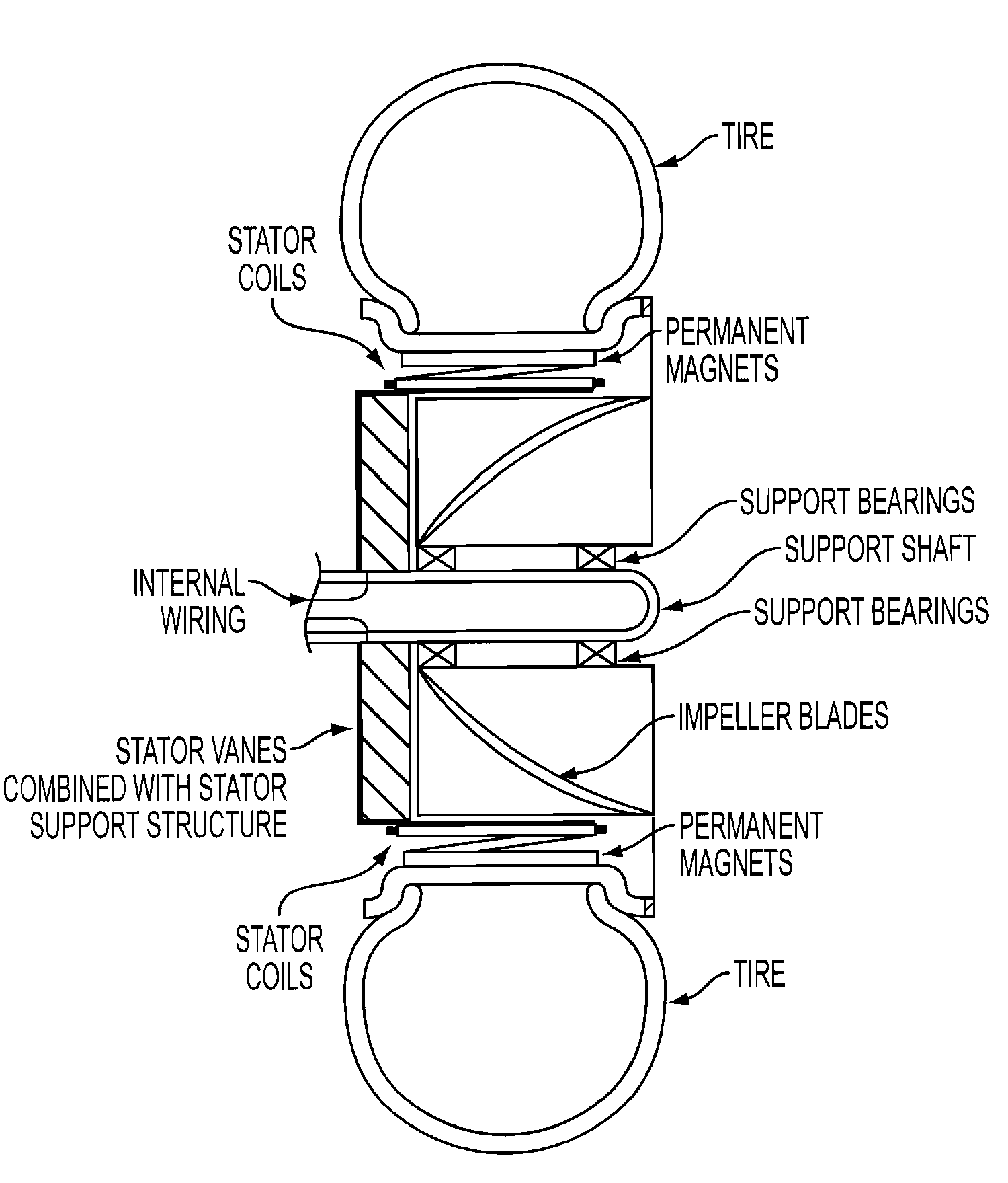
[0042]Some of the embodiments of the presently disclosed apparatuses and methods include an improvement in marine drive systems for amphibious vehicle or marine vessel operation and control within intelligent motion control systems. There may be a total systems integration of electric in-wheel motor / generators or motor / generators with impellers that uses magnetic torque applications for motoring in water to match outlet nozzle geometry to maximize thrust to applied power and vehicle or vessel velocity, and match nozzle direction and sizing to heading and vehicle or vessel velocity. In certain embodiments, electric power for in wheel motor / generators or motor / generators from a generator may be powered with conventional internal combustion engines or other type of engine such as a turbine and / or other stored electrical power. Fully integrated electrical torque applications of in-wheel motor / generators or motor / generators may be delivered with sufficient power density to effectively br...


PUM


Abstract

The methods and apparatuses of the present invention provides for powering and maneuvering (forward, reverse and steering) systems for amphibious vehicle, marine vessel or ground vehicle operation and control. An improved propulsion system may incorporate the use of electric motors combined with impellers which use positive and negative magnetic torque applications and allows for new control strategies when used in water or on the ground. More precise control of the motoring and steering forces is provided which is suitable for use in a variety of amphibious, marine vessels or ground vehicle applications. Various types of electric drive motor/generators may be incorporated for use therein. Intelligent motion control systems may provide for improved vehicle control that can provide motive force and braking force in a precisely controlled manner that significantly improves performance and has faster control dynamics incorporating a fully integrated electrical braking and maneuvering system.

Description

[0001]This is a non-provisional patent application claiming priority to U.S. Provisional Patent Application No. 61 / 021,970 filed Jan. 18, 2008, the entire disclosure of which is incorporated herein by reference. In addition, the entire disclosure of U.S. patent application Ser. No. 11 / 924,653 filed Oct. 26, 2007 is incorporated herein by reference.[0002]This application includes material which is subject to copyright protection. The copyright owner has no objection to the facsimile reproduction by anyone of the patent disclosure, as it appears in the Patent and Trademark Office files or records, but otherwise reserves all copyright rights whatsoever.FIELD OF THE INVENTION[0003]The present invention relates in general to powering and maneuvering (forward, reverse and steering) systems for amphibious vehicles, marine vessel operation or ground vehicle operation and control, and more specifically to an improved propulsion system that incorporates the use of electric motors combined wit...

Claims


Application Information

Patent Timeline
Patent Type & Authority Applications(United States)
IPC IPC(8): B63H21/17B60F3/00F03B13/00
CPCB60F3/0007
Inventor SULLIVAN, STEVEN
Owner SULLIVAN & COMPANY
Why Eureka
Try Eureka