Cardiopulmonary resuscitation unit control apparatus

a control apparatus and cardiopulmonary resuscitation technology, applied in the field of controllers for cardiopulmonary resuscitation apparatuses, can solve the problems of insufficient patient recovery of spontaneous circulation, inability to generate 15-20% of normal cardiac output of standard cpr, etc., and achieve the effect of paying more attention to the care of patients and simple construction of the cardiopulmonary resuscitation

Inactive Publication Date: 2009-07-23
HUMED +1
View PDF6 Cites 29 Cited by
  • Summary
  • Abstract
  • Description
  • Claims
  • Application Information

AI Technical Summary

Benefits of technology

[0013]According to the aspects of the invention, automation and precise control can be realized in the cardiopulmonary resuscitation apparatus by using a driving unit for constricting the chest band of the cardiopulmonary resuscitation apparatus, locking, and pressing the chest by air pressure, and a control unit for controlling the driving unit according to a control signal.
[0014]Further, the air pressure used in driving the cardiopulmonary resuscitation apparatus is controlled so as to be also supplied to a line of artificial respiration, such that a simple construction of the cardiopulmonary resuscitation apparatus and automation of artificial respiration are obtained.
[0015]Further, it is possible to automatically perform chest pressure and artificial respiration corresponding to a predetermined number, by the control of the control unit.
[0016]In addition, if an operator selects a pressed depth, the control unit can precisely perform automatic control a descent depth of a pressure pad pressing the chest.
[0017]Thanks to the present invention, the operator does not have to care about the operation of the cardiopulmonary resuscitation apparatus while performing cardiopulmonary resuscitation, which allows the operator to pay more attention in taking care of a patient.

Problems solved by technology

However, standard CPR can usually generate only 15-20% of normal cardiac output, which is inadequate to restore spontaneous circulation in the majority of patients.

Method used


Image

  • Cardiopulmonary resuscitation unit control apparatus
  • Cardiopulmonary resuscitation unit control apparatus
  • Cardiopulmonary resuscitation unit control apparatus

Examples


Embodiment Construction

[0024]Hereinafter, a preferred embodiment of the invention will be described in detail with reference to the accompanying drawings.

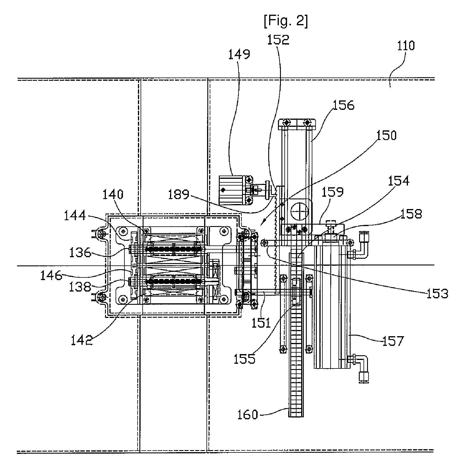
[0025]FIG. 1 is a longitudinal cross-section view of a cardiopulmonary resuscitation apparatus according to the present invention, and FIG. 2 is a transverse cross-section view of the cardiopulmonary resuscitation apparatus according to the present invention.

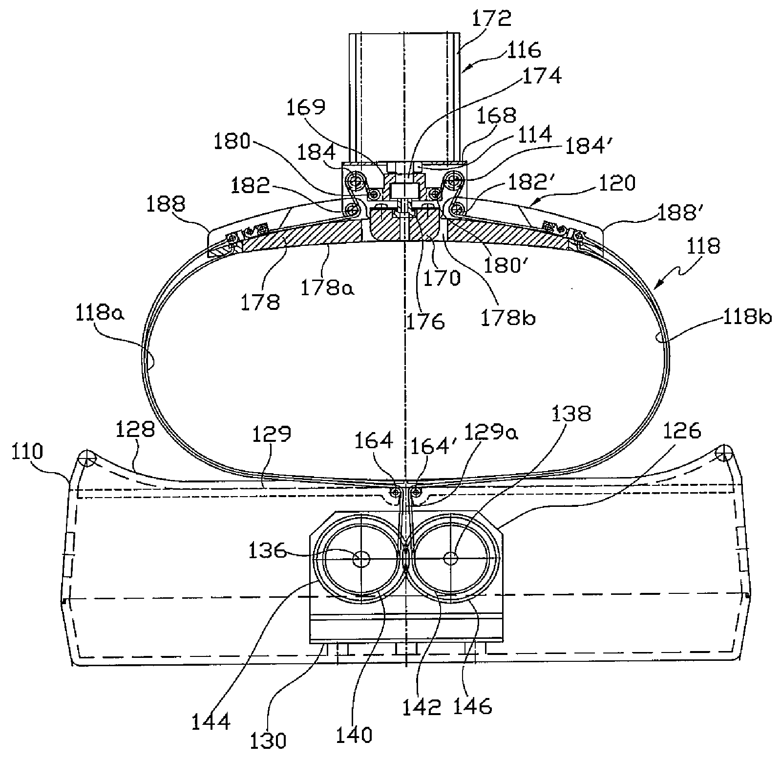
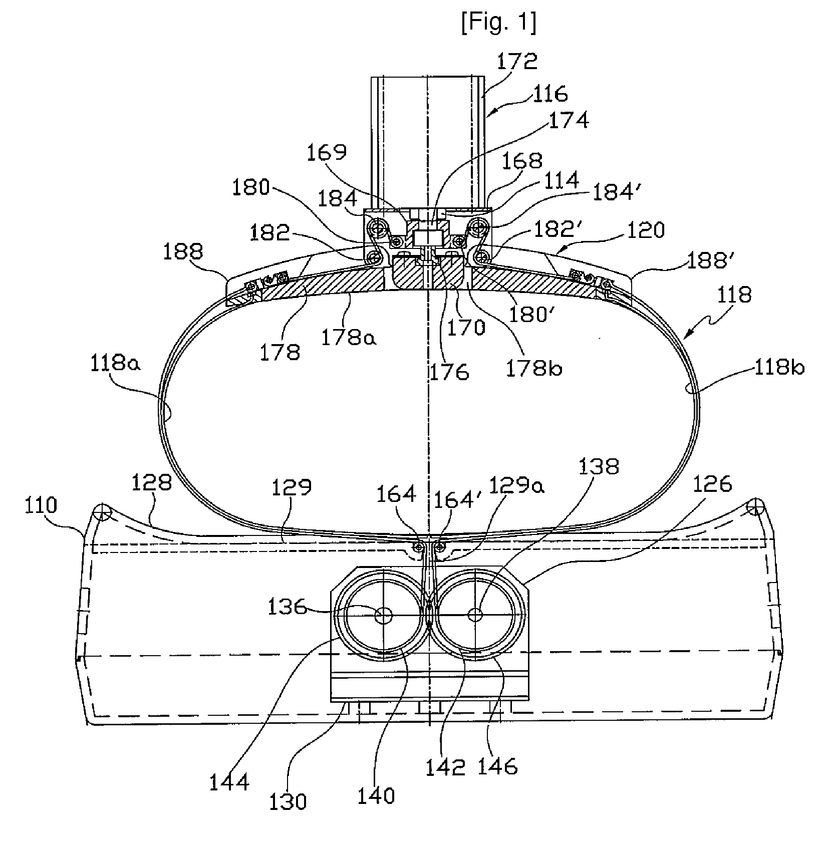
[0026]As shown in FIGS. 1 and 2, the cardiopulmonary resuscitation apparatus according to the invention includes a main body 110 where a patient lies, a first pressure unit 116 having a piston 114 that presses the patient's chest, a second pressure unit 120 that is coupled with the first pressure unit 116 and has a chest band 118 for wrapping around the patient's chest, and a length adjusting unit 126 in the main body 110, for controlling the length of the chest band 118 according to the size of the patient's chest.

[0027]The chest band 118 is divided into left and right chest bands 118a and 118b for ...


PUM


Abstract

The present invention relates to a controller for a cardiopulmonary resuscitation apparatus. Automation and precise control can be realized in the cardiopulmonary resuscitation apparatus by using a driving unit involving in constricting the chest band of the cardiopulmonary resuscitation apparatus, locking, and pressing the chest by air pressure, and a control unit controlling the driving unit according to a control signal. Further, air pressure used in driving the cardiopulmonary resuscitation apparatus is controlled so as to be also supplied to a line of artificial respiration, such that a simple construction of the cardiopulmonary resuscitation apparatus and automation of artificial respiration are obtained. Thanks to the present invention, the operator does not have to care about the operation of the cardiopulmonary resuscitation apparatus while performing cardiopulmonary resuscitation, which allows the operator pay more attention to taking care of a patient.

Description

TECHNICAL FIELD[0001]The present invention relates to a controller for a cardiopulmonary resuscitation (CPR) apparatus, more particularly, to a controller for a cardiopulmonary resuscitation apparatus capable of precisely controlling a CPR apparatus by automation.BACKGROUND ART[0002]Generally, the method of cardiopulmonary resuscitation provides oxygenated blood flow to the entire body of a patient whose heartbeat has stopped, in lieu of heart and lung, which involves external chest pressure and artificial respiration.[0003]In order to restore spontaneous blood circulation, coronary perfusion pressure needs to be maintained above 20 mmHg during cardiopulmonary resuscitation. However, standard CPR can usually generate only 15-20% of normal cardiac output, which is inadequate to restore spontaneous circulation in the majority of patients. Therefore, a variety of CPR apparatuses have been disclosed to enhance the amount of blood flow.[0004]Examples of the CPR apparatuses were filed by ...

Claims


Application Information

Patent Timeline
Patent Type & Authority Applications(United States)
IPC IPC(8): A61H31/02
CPCA61H31/006A61H31/008A61M16/00A61H2201/5064A61H2201/5071A61H2201/5007A61H31/00A61H2201/0184A61H2201/5023A61H2203/0456A61H2205/082
Inventor HWANG, SUNG-OHKIM, WON-CHUL
Owner HUMED
Why Eureka
Try Eureka