Cylinder head gasket

a gasket and cylinder head technology, applied in the direction of engine seals, machine/engines, etc., can solve the problems of increasing the surface pressure on the cylinder periphery portion, increasing the gap between the cylinder block and the cylinder head, and increasing the relative movement, so as to secure stable sealing performance, reduce deviation, and heighten the follow-up characteristic

Active Publication Date: 2009-07-30
TOYOTA JIDOSHA KK +1
View PDF6 Cites 24 Cited by
  • Summary
  • Abstract
  • Description
  • Claims
  • Application Information

AI Technical Summary

Benefits of technology

[0009]It is an object of the invention to provide a cylinder head gasket that secures stable sealing performance by reducing the deviation between adjacent gasket base plates whi

Problems solved by technology

Due to the trend toward increased in-cylinder pressures, there is a tendency toward increased relative movements between the cylinder block and the cylinder head and, therefore, increased amounts of gap between the cylinder block and the cylinder head.
According to the cylinder head gasket described in Japanese Patent No. 2935544, since the thickness of the gasket subsidiary plate is greater in the cylinder periphery portion-side region than in the region outward of the cylinder periphery portion-side region, the surface pressure on the cylinder periphery portion can be increased; however, the following problems occur.
Since the cylinder periphery portion-side region of the gasket subsidiary plate and the region outward of the cylinder periphery portion-side region are provided as a single member, it is difficult in an application to a multi-cylinder engine to vary the thickness of the cylinder periphery portion-side region of the ga

Method used


Image

  • Cylinder head gasket
  • Cylinder head gasket
  • Cylinder head gasket

Examples


Embodiment Construction

[0027]Best forms for carrying out the invention will be described with reference to the accompanying drawings.

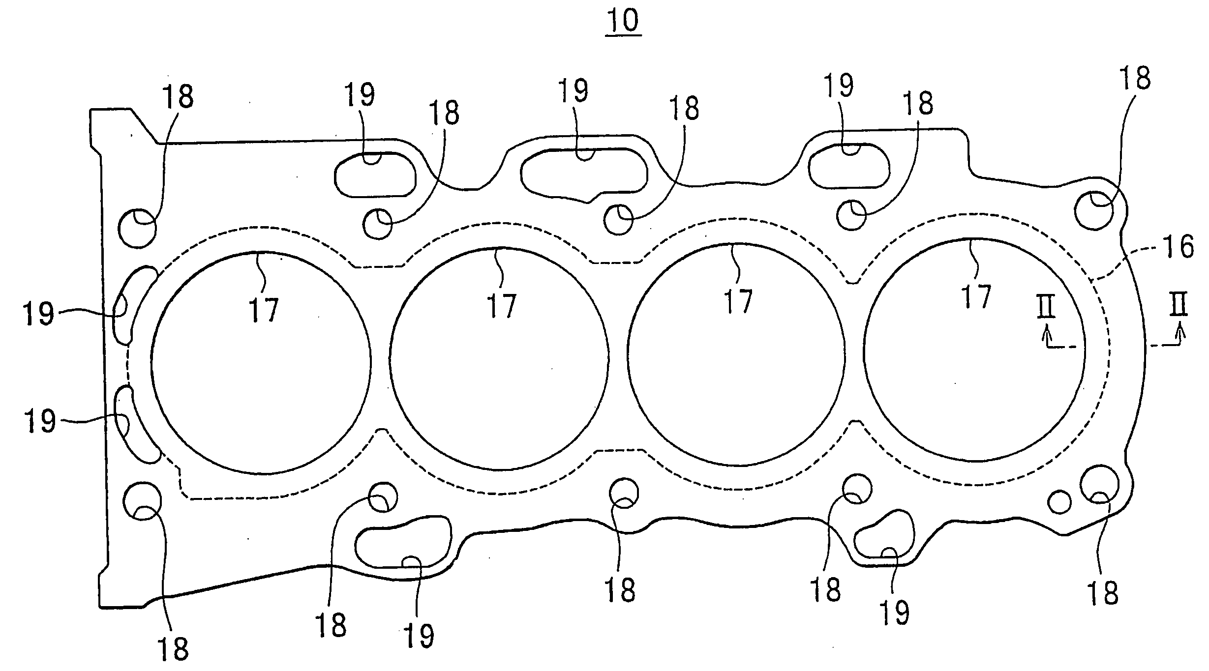
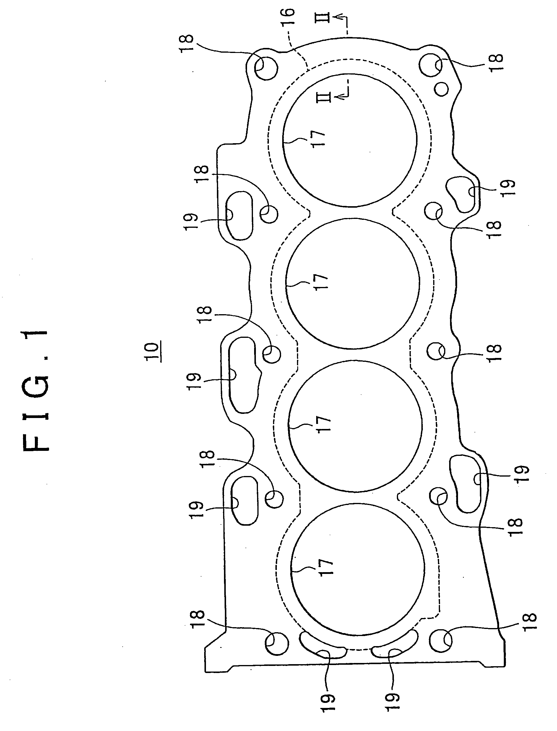
[0028]FIGS. 1 and 2 show a cylinder head gasket for an in-line four-cylinder diesel engine (hereinafter, referred to as “engine”). A cylinder head gasket 10 in this example is disposed between a cylinder block 2 and a cylinder head (not shown) of an engine 1. Then, by integrally uniting the lower-side cylinder block 2 disposed and the upper-side cylinder head via fastening bolts, the cylinder head gasket 10 is sandwiched between the cylinder block 2 and the cylinder head, so that the gap between the cylinder block 2 and the cylinder head is sealed.

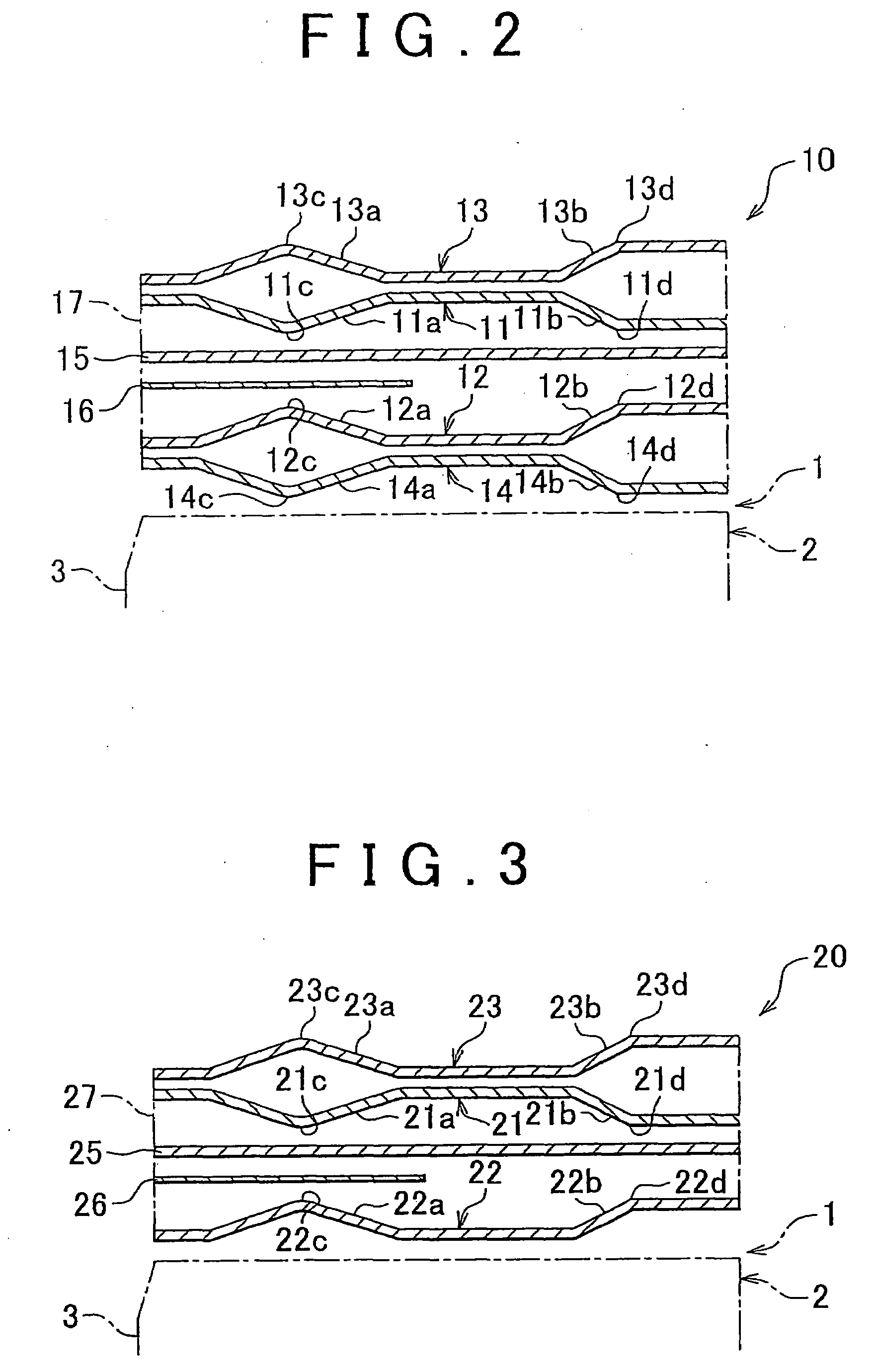
[0029]The cylinder head gasket 10 includes a plurality of gasket base plates (first to fourth gasket base plates 11 to 14) that are stacked together with a shim 15 and a pressure increasing plate 16 on top of one another. The gasket base plates, the shim 15 and the pressure increasing plate 16 are integrally fastened together by kn...


PUM


Abstract

A cylinder head gasket includes a first gasket base plate at a cylinder head side, a second gasket base plate at a cylinder block side, a shim that adjusts the gasket thickness, and a pressure increasing plate that increases the surface pressure at the side of periphery portions of the cylinders. In the first and second gasket base plates full beads are swollen at the side of periphery portions of cylinders, and half beads are swollen at a site outward of the full beads. The full beads of the first and second gasket base plates are formed so that top portions of the full beads face each other at positions that are opposite to each other in the up-down direction. The shim and the pressure increasing plate are sandwiched between the top portions.

Description

BACKGROUND OF THE INVENTION[0001]1. Field of Invention[0002]The invention relates to a cylinder head gasket disposed between a cylinder block and a cylinder head of an engine.[0003]2. Description of Related Art[0004]In recent years, in association with improvements in the performance of motor vehicle-purpose engines and, particularly, diesel engines, the combustion pressure of the engines is increasing, and a trend toward increased in-cylinder pressures of the engines is progressing. Due to the trend toward increased in-cylinder pressures, there is a tendency toward increased relative movements between the cylinder block and the cylinder head and, therefore, increased amounts of gap between the cylinder block and the cylinder head. This leads to higher requirements for the sealing performance provided by a cylinder head gasket interposed between the cylinder block and the cylinder head.[0005]An example of a cylinder head gasket in which the sealing performance of a cylinder peripher...

Claims


Application Information

Patent Timeline
IPC IPC(8): F02F11/00
CPCF16J15/0825F16J2015/0862F16J2015/085F02F11/00F16J15/08
Inventor YOSHIJIMA, KAZUYATAKEDA, YASUMAROKIYOI, SHIGEO
Owner TOYOTA JIDOSHA KK
Why Eureka
Try Eureka