High dynamic range ask demodulator for use in an RFID transponder

a demodulator and dynamic range technology, applied in pulse manipulation, pulse technique, instruments, etc., can solve the problems of small drain-source and gate voltage, too high swing in a range of 8v for integrated cmos circuits implemented in advanced cmos technology, and severe clamping of voltage swing from ask downlink modulation, etc., to achieve stable demodulator sensitivity

Active Publication Date: 2009-07-30
TEXAS INSTR INC
View PDF3 Cites 14 Cited by
  • Summary
  • Abstract
  • Description
  • Claims
  • Application Information

AI Technical Summary

Benefits of technology

[0006]Specifically, the present invention provides an ASK demodulator for use in an RFID transponder, comprising a limiter circuit associated with the antenna circuit and converting the ASK antenna field strength modulation into an ASK limiter current modulation by limiting the antenna voltage to a fixed value and thereby causing the limiter current to be substantially proportional to the ASK antenna field strength, and a current discriminator circuit that discriminates the ASK limiter current modulation. By converting the field strength modulation into a proportional limiter current and discriminating that limiter current—or a copy of that current—, a linear relationship and a stable demodulator sensitivity are achieved. The current discrimination can be made accurately under low-voltage conditions.

Problems solved by technology

However, advanced CMOS technologies allow only small drain-source and gate voltages.
A voltage swing in a range of 8V is too high for integrated CMOS circuits implemented in an advanced CMOS technology, especially when a low cost process is used which does not support high voltage transistors or high precision capacitors for use in a resonant circuit.
Accordingly, the voltage swing from an ASK downlink modulation will be severely clamped, and a direct envelope demodulation will not work any more.

Method used


Image

  • High dynamic range ask demodulator for use in an RFID transponder
  • High dynamic range ask demodulator for use in an RFID transponder
  • High dynamic range ask demodulator for use in an RFID transponder

Examples


Embodiment Construction

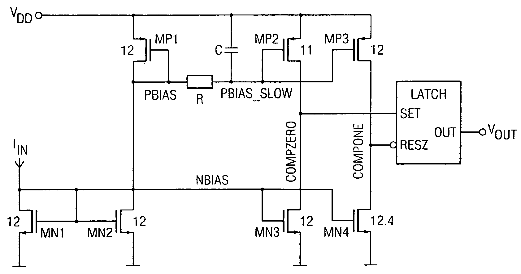
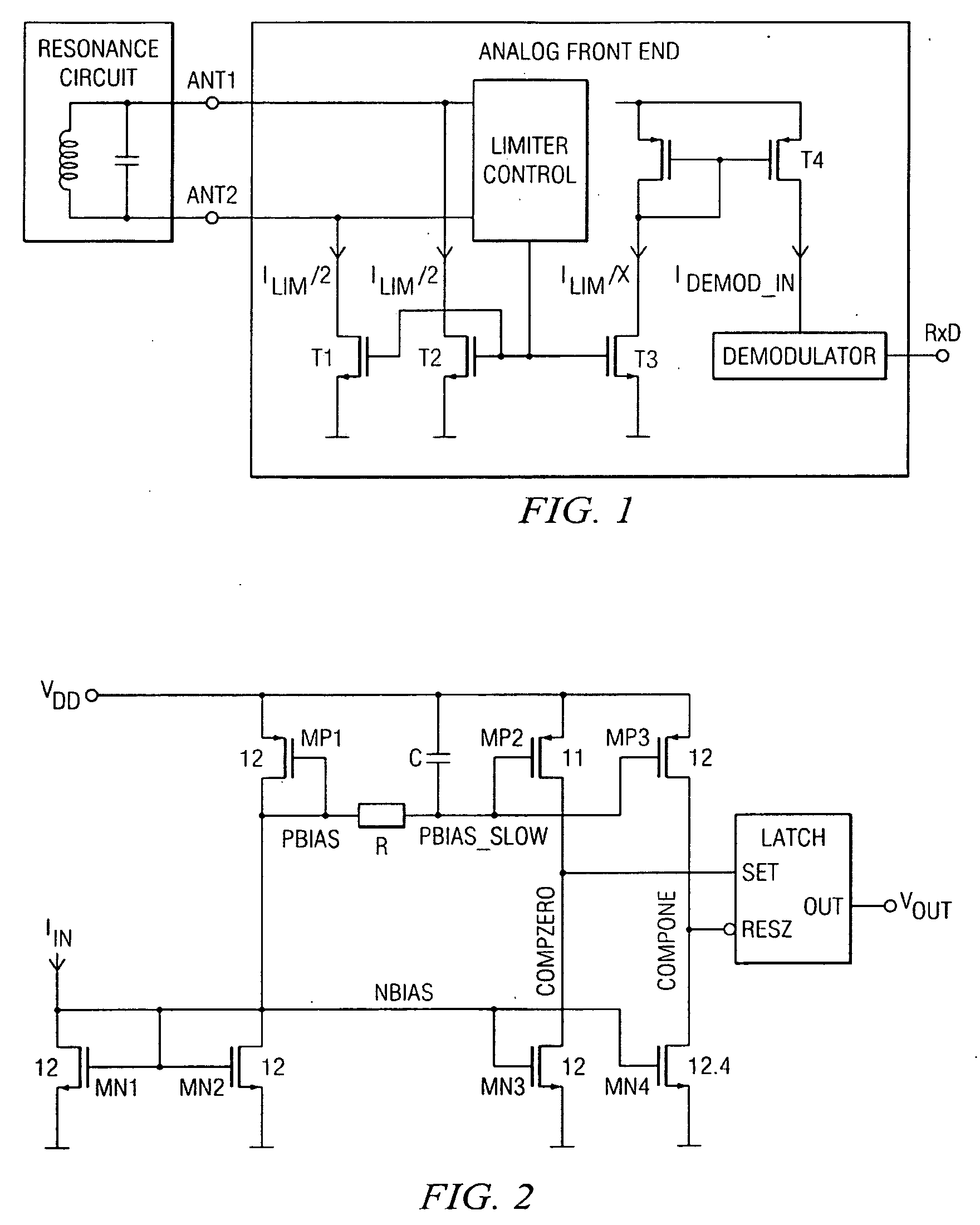
[0019]With reference first to FIG. 1, a transponder has an external LC resonance circuit and an analog front end with input terminals Ant1 and Ant2 connected to the LC resonance circuit. Each of the input terminals Ant1 and Ant2 has an associated limiting transistor T1, T2 the gates of which are interconnected and driven by a limiter control block which is also connected to both input terminals Ant1 and Ant2. Each of the transistors T1 and T2 draws half of the limiter current, ILIM / 2. A transistor T3 mirrors the limiter current ILIM / 2 to ILIM / x and a further transistor T4 mirrors the current ILIM / x to IDEMOD—IN, which is the input current IIN to the ASK demodulator circuit of FIG. 2. The output signal R×D of the ASK demodulator corresponds to the output signal VOUT in FIG. 2.

[0020]The ASK demodulator in FIG. 2 receives as its input IIN the copied limiter current IDEMOD—IN from the voltage limiter circuit in FIG. 1. The input stage of the demodulator is a diode-connected NMOS transis...


PUM


Abstract

An ASK demodulator for use in an RFID transponder having a limiter circuit associated with the antenna circuit and converting the ASK antenna fieldstrength modulation into an ASK limiter current modulation by limiting the antenna voltage to a fixed value and thereby causing the limiter current to be substantially proportional to the ASK antenna field strength, and a current discriminator circuit that discriminates the ASK limiter current modulation. By converting the fieldstrength modulation into a proportional limiter current and discriminating that limiter current, a linear relationship and a stable demodulator sensitivity are achieved. The current discrimination can be made accurately under low-voltage conditions.

Description

FIELD OF THE INVENTION[0001]The present invention relates to an ASK demodulator for use in an RFID transponder.BACKGROUND OF THE INVENTION[0002]The analog front end of an RFID transponder includes a resonant LC antenna circuit. In high frequency RFID transponders the resonant frequency is typically 13 MHz. The antenna captures the modulated RF field from an interrogator (ASK downlink modulation) giving rise to a fairly high antenna voltage with voltage swings in the range of 8V. An antenna voltage in the range of 8V allows a straight forward envelope detection for demodulation with a conventional CMOS circuit used in the RFID transponder.[0003]However, advanced CMOS technologies allow only small drain-source and gate voltages. A voltage swing in a range of 8V is too high for integrated CMOS circuits implemented in an advanced CMOS technology, especially when a low cost process is used which does not support high voltage transistors or high precision capacitors for use in a resonant ...

Claims


Application Information

Patent Timeline
Patent Type & Authority Applications(United States)
IPC IPC(8): H03K9/02
CPCG06K19/0723H04L27/06H03K5/082H03D1/18
Inventor NEHRIG, OLIVIERPESCHKE, CARLOMUELLNER, ERNSTBAUMANN, ADOLFGRAUL, JENS
Owner TEXAS INSTR INC
Why Eureka
Try Eureka