Outboard motor with reverse shift

a technology of reverse shift and outboard motor, which is applied in the direction of outboard propulsion units, marine propulsion, and vessel construction, can solve the problems of large motors that allow the reverse movement of boats, complicated gear-switching mechanisms, and difficult forward movement, and achieve the effect of preventing propeller damag

Inactive Publication Date: 2009-07-30
PROVOST BRIAN
View PDF13 Cites 0 Cited by
  • Summary
  • Abstract
  • Description
  • Claims
  • Application Information

AI Technical Summary

Benefits of technology

[0007]The present invention contemplates elimination of drawbacks associated with the conventional outboard motor unit and provision of an outboard drive unit that can be inexpensively modified or retrofitted to allow changing of the shift position between a forward shift position and a reverse shift position in an easy manner.
[0009]It is another object of the present invention to provide an outboard drive unit that allows equalization of pressure between the exterior and interior of the gearbox and allows the hot air to escape the gearbox at a point above the water surface.
[0010]It is still another object of the present invention to provide a skeg extension member which allows the outboard motor to be mounted on tall transom boats.
[0016]An optional stabilizing member is secured on the skeg to compensate for directional force acting on said outboard motor drive unit during rotation of the propeller. The outboard motor unit of the instant invention may be optionally equipped with a detachably securable propeller guard assembly for preventing damage of the propeller by hard objects located in a body of water.

Problems solved by technology

The larger motors that allow reverse movement of the boat are typically large, expensive, and have complicated gear-switching mechanisms.
An additional problem experienced by motor craft when running in shallow or muddy waters, is that the water body has overgrowth of vegetation which catches on the propeller and makes forward movement extremely difficult.
Another problem is the possibility of the propeller striking rocks or other hard underwater objects causing severe damage to the propeller unit.
Still another problem that is encountered when using a small outboard motor unit is that when it is mounted on a tall transom boat the skeg of the propeller is insufficiently submerged to provide an effective steering on the water.
A further problem experienced with outboard motor units is the buildup of pressure inside the gearbox and the stuffing box, which results from the rotation of the shaft and the gears.
The buildup of hot air pressure causes the seals to leak and allows water to enter resulting in inevitable danger to bearings and the gear.

Method used


Image

  • Outboard motor with reverse shift
  • Outboard motor with reverse shift
  • Outboard motor with reverse shift

Examples


Embodiment Construction

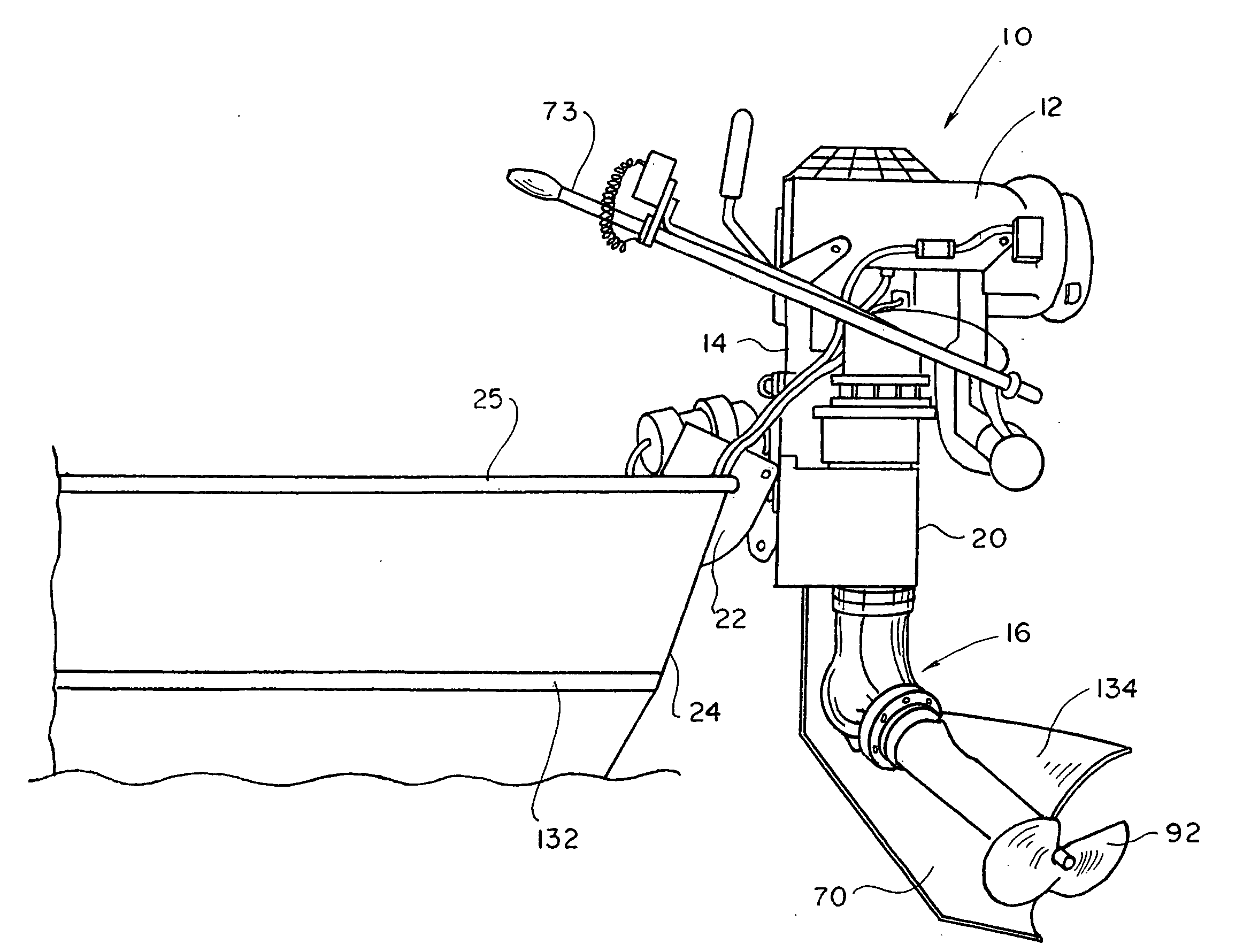
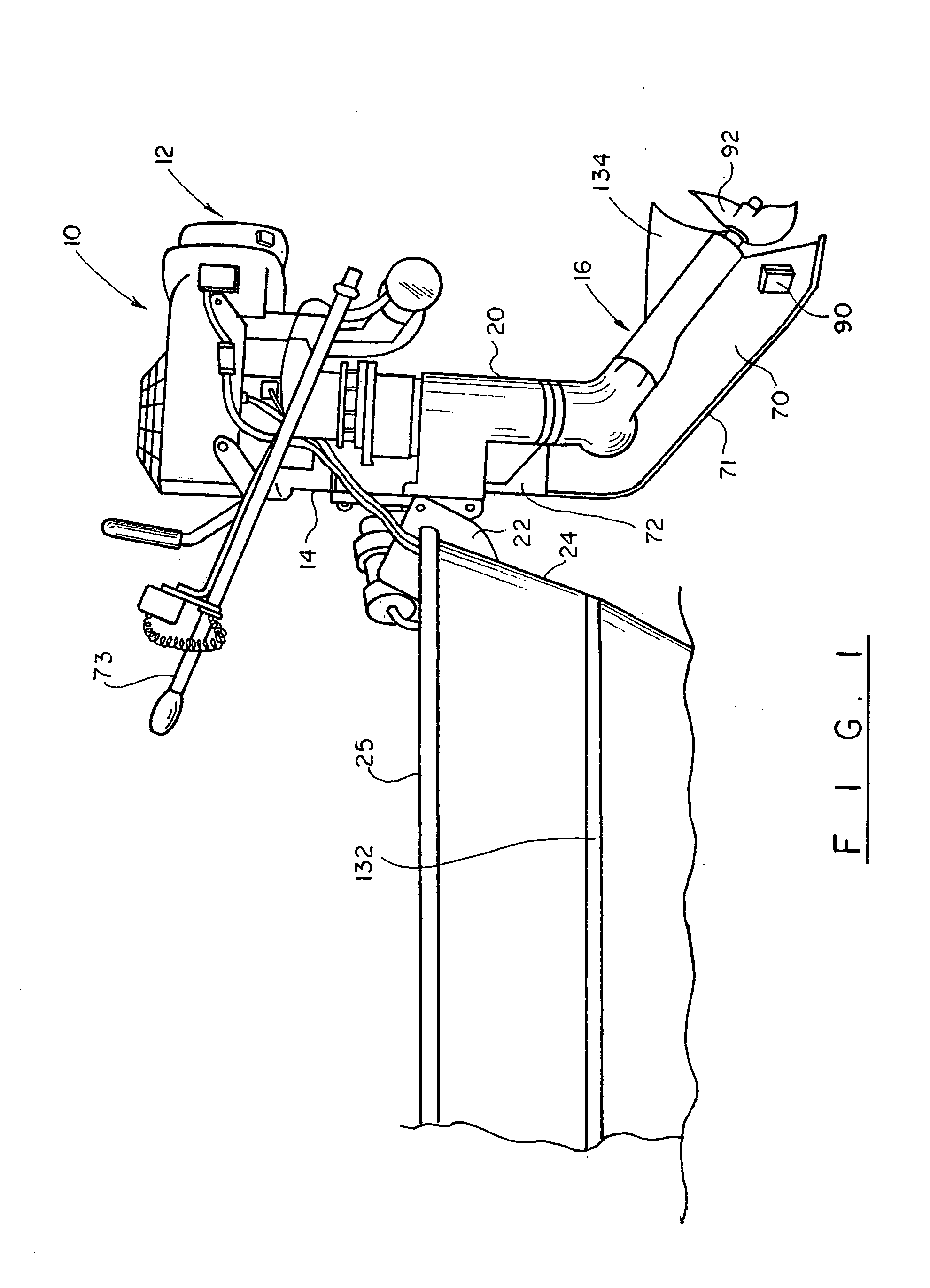
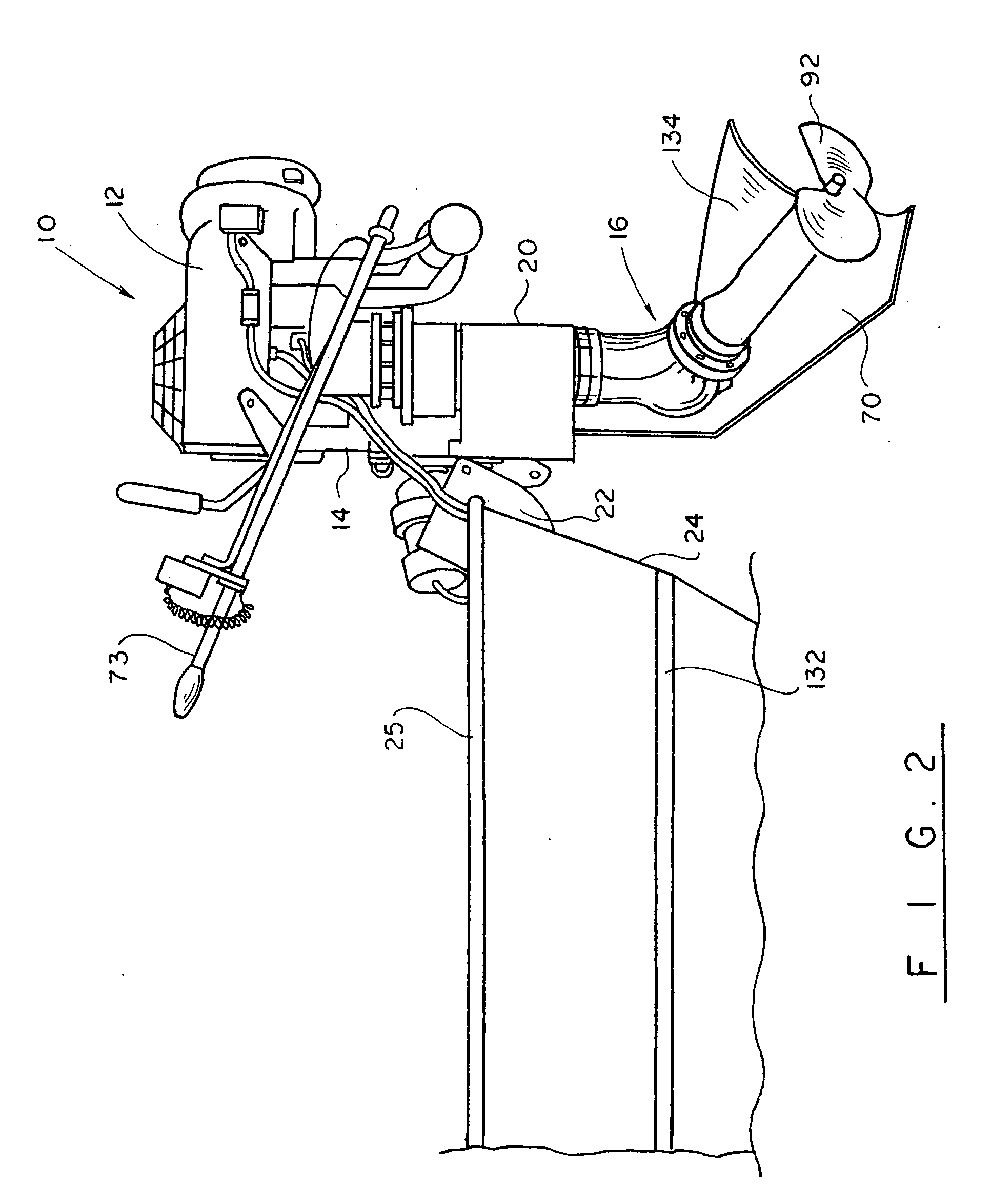
[0033]Turning now to the drawings in more detail, numeral 10 designates the outboard drive unit of the present invention. The outboard motor 10 comprises an upper unit, or power head 12, the drive shaft housing 14, and the lower unit 16. The upper unit 12 includes an internal combustion engine of a conventional design, for instance an inline two-cylinder engine that operates on a 4-stroke combustion principle. Similar to conventional engines, the engine employed in the design of the present invention has reciprocating cylinders moving within the combustion chambers and moving a drive shaft 18. The drive shaft transmits rotational force to the lower unit 16 through an input shaft 18 mounted in the lower unit housing 20. The engine 12 is connected to a fuel supply system (not shown) that supplies the fuel charge to the combustion chambers for allowing blending of the fuel and release of gases out of the combustion chambers. Although not shown, it is within the knowledge of those skill...


PUM


Abstract

An outboard motor for small watercraft, such as a pleasure boat, has a capability of changing between a forward shift position and a reverse shift position by causing a lower part of the unit to rotate in small increments and move along an arc formed by a ratchet plate secured above the propeller assembly.

Description

CROSS REFERENCE TO RELATED APPLICATIONS[0001]This application is a continuation of my co-pending application Ser. No. 11 / 879,112 filed on Jul. 16, 2007, which is a continuation-in-part of my co-pending application Ser. No. 11 / 698,003 filed on Jan. 24, 2007 (abandoned), which is a continuation of application Ser. No. 11 / 156,184, filed on Jun. 20, 2005, now abandoned, which is a continuation of application Ser. No. 10 / 389,157 filed on Mar. 14, 2003, now U.S. Pat. No. 6,921,305, the full disclosures of which are incorporated by reference herein and the priority of which is hereby claimed.BACKGROUND OF THE INVENTION[0002]This invention relates to outboard motors, and more particularly to a drive unit for use with the watercraft, such as a pleasure boat, with the capability to shift gears between a forward position and a reverse position.[0003]Conventional marine outboard drive units are supported on the transom of a boat and can be pivoted to move in a generally horizontal plane, left a...

Claims


Application Information

Patent Timeline
Patent Type & Authority Applications(United States)
IPC IPC(8): B63H20/08
CPCB63H1/18B63H5/125B63H20/08B63H20/10B63H2001/185B63H20/32B63H20/34B63H20/36B63H20/12
Inventor PROVOST, BRIAN
Owner PROVOST BRIAN
Why Eureka
Try Eureka