Intermittent gas flow apparatus and membrane separation apparatus

a gas flow apparatus and membrane separation technology, applied in the direction of membranes, sustainable biological treatment, biological water/sewage treatment, etc., can solve the problems of complex structure, increased cost, and shortened life of hollow fiber membranes, and achieves simple construction and prolonging the life of filtration membranes.

Inactive Publication Date: 2009-08-06
ASAHI KASEI CHEM CORP
View PDF3 Cites 112 Cited by
  • Summary
  • Abstract
  • Description
  • Claims
  • Application Information

AI Technical Summary

Benefits of technology

[0036]The present invention described above enables intermittent aeration operation with a simple const...

Problems solved by technology

When continuous aeration is performed, however, electricity expenses are incurred to constantly supply air, and life of hollow fiber membranes is shortened due to damage from being continuously aerated.
Such a separate control...

Method used


Image

  • Intermittent gas flow apparatus and membrane separation apparatus
  • Intermittent gas flow apparatus and membrane separation apparatus
  • Intermittent gas flow apparatus and membrane separation apparatus

Examples


first embodiment

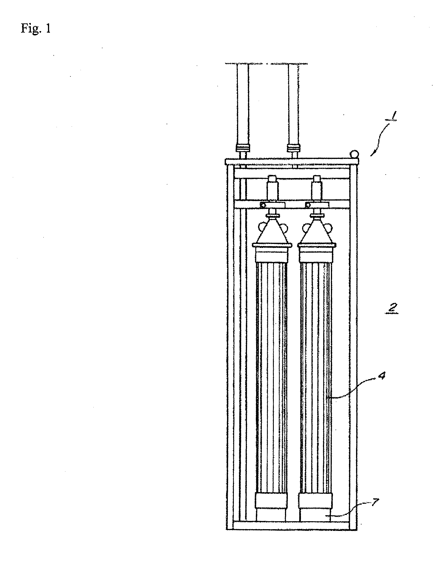
[0066]In FIGS. 1 through 3F, a membrane separation unit 1 filtering and separating liquid in a treatment tank 2 is provided with a plurality of hollow fiber membrane modules 4. In the membrane separation unit 1, liquid is pumped through hollow fiber membranes 3, which are submerged in the liquid in the treatment tank 2 and function as filtration membranes.

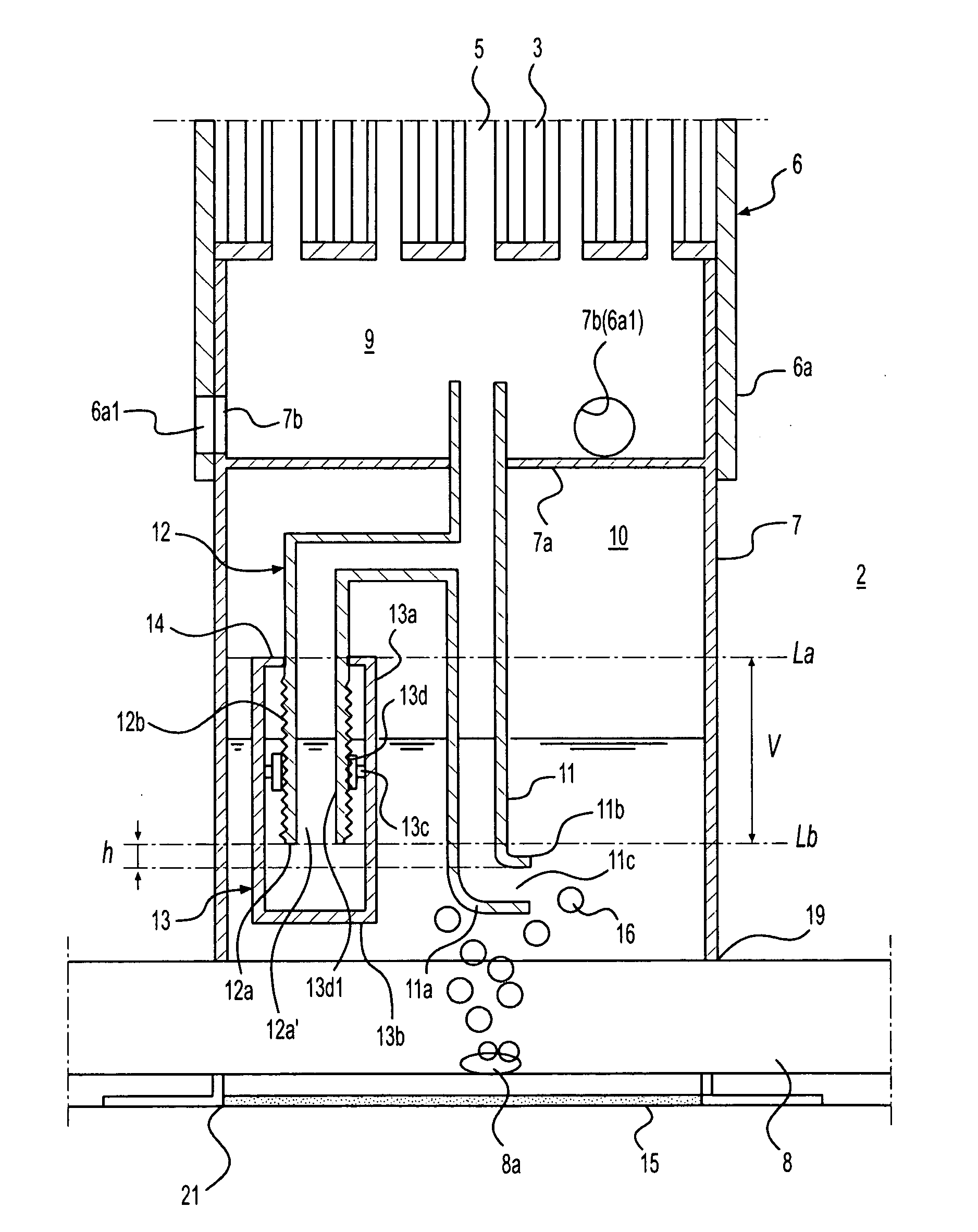
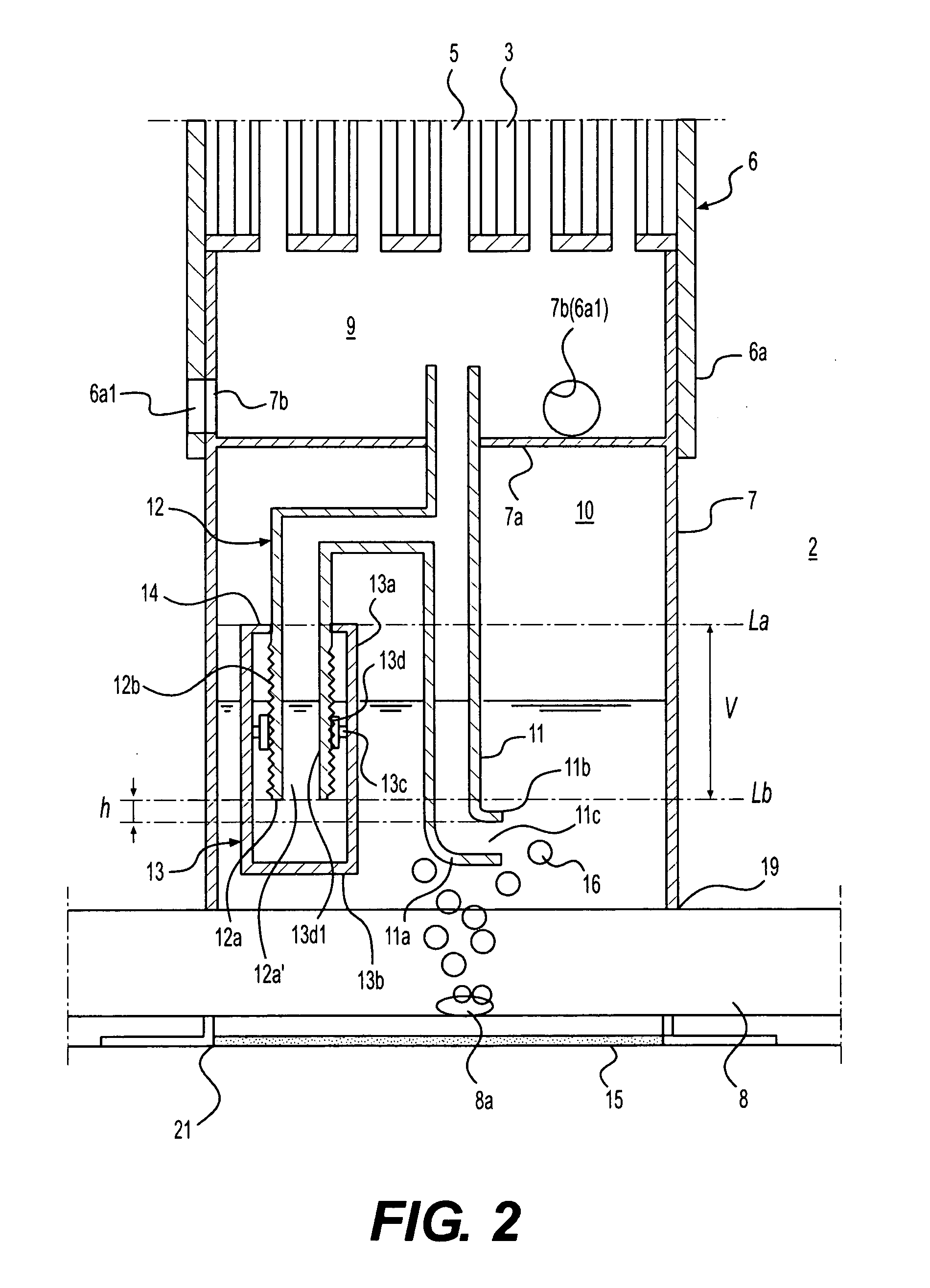
[0067]The membrane separation unit 1 includes a bundled portion 6, an intermittent gas flow apparatus in a form of a pedestal member 7, and an aeration pipe 8. The bundled portion 6 is provided with openings for aeration 5, which are disposed at predetermined positions, so as to avoid positions to which end portions of the plurality of hollow fiber membranes 3 are fixed. The pedestal member 7, which is provided in contact with the bundled portion 6, receives at least self weight of the plurality of hollow fiber membranes 3 as well as serves as a container that constitutes an air chamber below the bundled portion 6. Thus, the bundle...

second embodiment

[0088]FIG. 4 is a schematic cross-sectional view illustrating a structure of a membrane separation unit according to a second embodiment of the present invention. Components identically structured to those in the first embodiment are indicated with identical numerical references, and explanations thereof are omitted. In the present embodiment, the aeration pipe 8b as a gas supplier is linked to a side wall 7c of the second air chamber 10 of the pedestal member 7 as a container, so that air (gas) is released into the second air chamber 10. In this case, the aeration pipe 8 provided below the pedestal member 7 may be eliminated or used along with the aeration pipe 8b linked to the second air chamber 10, as shown in FIG. 4. The structure of remaining components is the same as that in the first embodiment, and the same effects can be obtained.

third embodiment

[0089]FIG. 5 is a schematic cross-sectional view illustrating a structure of a membrane separation unit according to a third embodiment of the present invention. Components identically structured to those in the first embodiment are indicated with identical numerical references, and explanations thereof are omitted. In the previous embodiment, the auxiliary pipe 12 is branched from the column pipe 11 in the second air chamber 10. In the present embodiment, however, the auxiliary pipe 12′ is passed through the partition panel 7a and extended to the first air chamber 9. The auxiliary pipe 12′ is branched from the column pipe 11 in the first air chamber 9. The structure of remaining components is the same as that in the first embodiment, and the same effects can be obtained.


PUM


Abstract

Intermittent gas flow and membrane separation apparatus and methods of use including an internal gas chamber including an upper wall; at least one inlet for supplying gas to the internal gas chamber; a column pipe that extends above the upper wall of the internal gas chamber, the column pipe including a lower end portion including a lower end portion opening in the internal gas chamber, the column pipe linking the internal gas chamber to an area external to the internal gas chamber for fluid flow between the internal gas chamber and the external area; an auxiliary pipe including one end portion connected to the column pipe for fluid flow between the auxiliary pipe and the column pipe, and another end portion branched off from the column pipe, the another end portion including an opening located in the internal gas chamber at a position higher than the lower end portion opening of the column pipe by a predetermined height; and an auxiliary pipe external tubular member including a closed end, the auxiliary pipe external tubular member surrounding the another end portion of the auxiliary pipe with the closed end being positioned below the opening in the another end portion of the auxiliary pipe, and spaced from the another end portion by a predetermined distance permitting fluid flow into the space between the wall of the tubular member and the auxiliary pipe.

Description

CROSS-REFERENCE TO RELATED APPLICATIONS[0001]The present application claims priority under 35 U.S.C. §119 of Japanese Application No. 2008-004425, filed Jan. 11, 2008, the disclosure of which is expressly incorporated by reference herein in its entirety.BACKGROUND OF THE INVENTION[0002]1. Field of the Invention[0003]The present invention relates to intermittent gas flow units useful for providing intermittent flow of gas, which units are useful in any environment wherein an intermittent flow of gas is desired, for example, with membrane separation units to provide cleaning of the membrane separation units. The present invention also relates to membrane separation units, such as membrane separation units including a plurality of membrane modules, such as hollow fiber membrane modules. The present invention also relates to filtering and separating liquid in a treatment tank by performing suction through membranes, such as through hollow fiber membranes submerged in the liquid in the t...

Claims


Application Information

Patent Timeline
IPC IPC(8): B01D65/02F16K24/00B01D61/18
CPCB01D61/18B01D63/02C02F2303/16B01D2315/06C02F3/1273B01D2313/26B01D65/02B01D2321/185Y10T137/86292Y02W10/10
Inventor HASHIMOTO, TOMOTAKA
Owner ASAHI KASEI CHEM CORP
Why Eureka
Try Eureka