Coil assembly for electrical rotating machine, stator for electrical rotating machine, and electrical rotating machine

a technology of rotating machine and coil, which is applied in the direction of rotating parts of magnetic circuits, magnetic circuit shapes/forms/construction, windings, etc., can solve the problems of reducing output power, decrement of strength, and difficulty in allowing a large current to flow through, so as to stably hold the magnetic flux transfer member and suppress the space factor

a technology of rotating machine and coil, which is applied in the direction of rotating parts of magnetic circuits, magnetic circuit shapes/forms/construction, windings, etc., can solve the problems of reducing output power, decrement of strength, and difficulty in allowing a large current to flow through, so as to stably hold the magnetic flux transfer member and suppress the space factor

US20090195106A1Inactive Publication Date: 2009-08-06HONDA MOTOR CO LTD

Image

  • Coil assembly for electrical rotating machine, stator for electrical rotating machine, and electrical rotating machine
  • Coil assembly for electrical rotating machine, stator for electrical rotating machine, and electrical rotating machine
  • Coil assembly for electrical rotating machine, stator for electrical rotating machine, and electrical rotating machine

Examples


embodiment

[0071]With reference to the drawings will be described an embodiment of the present invention.

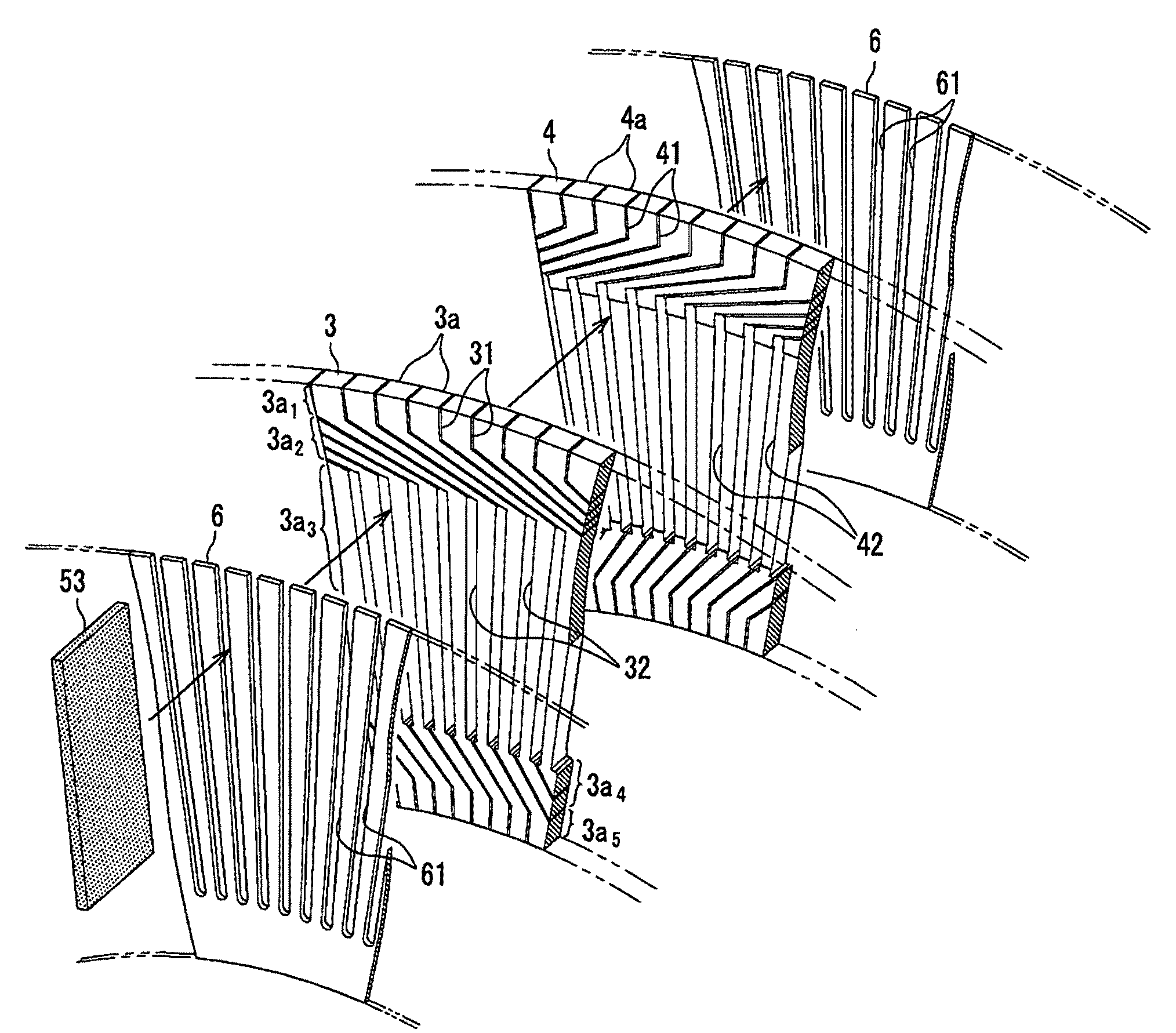
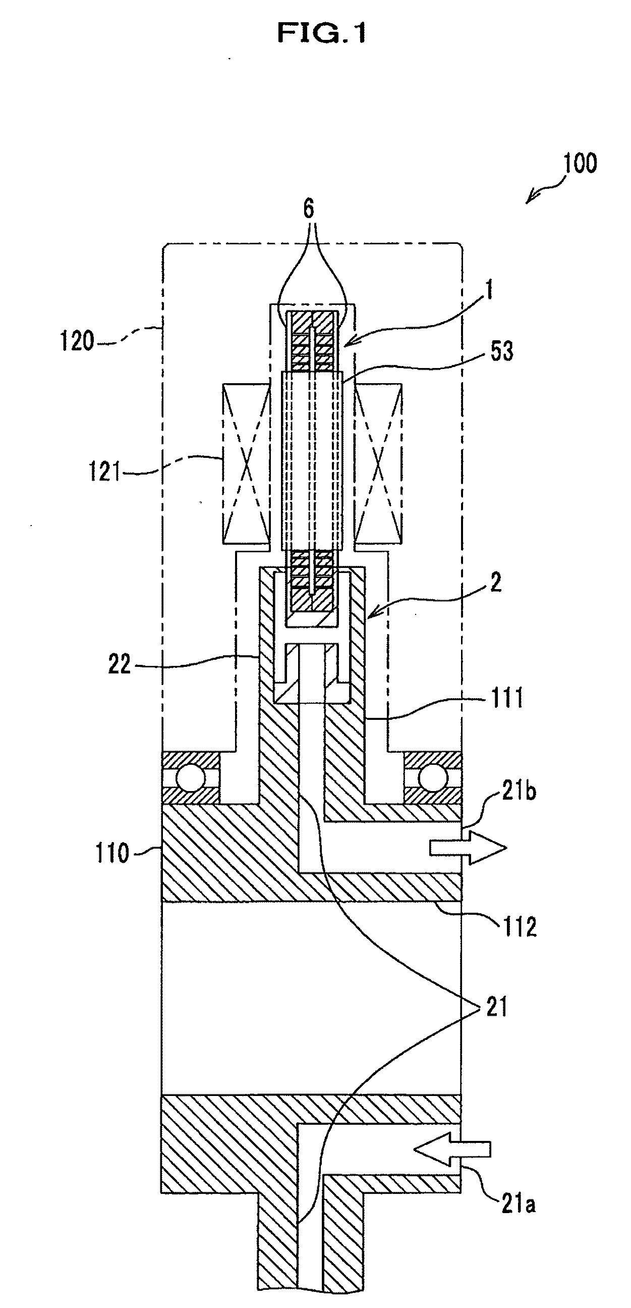
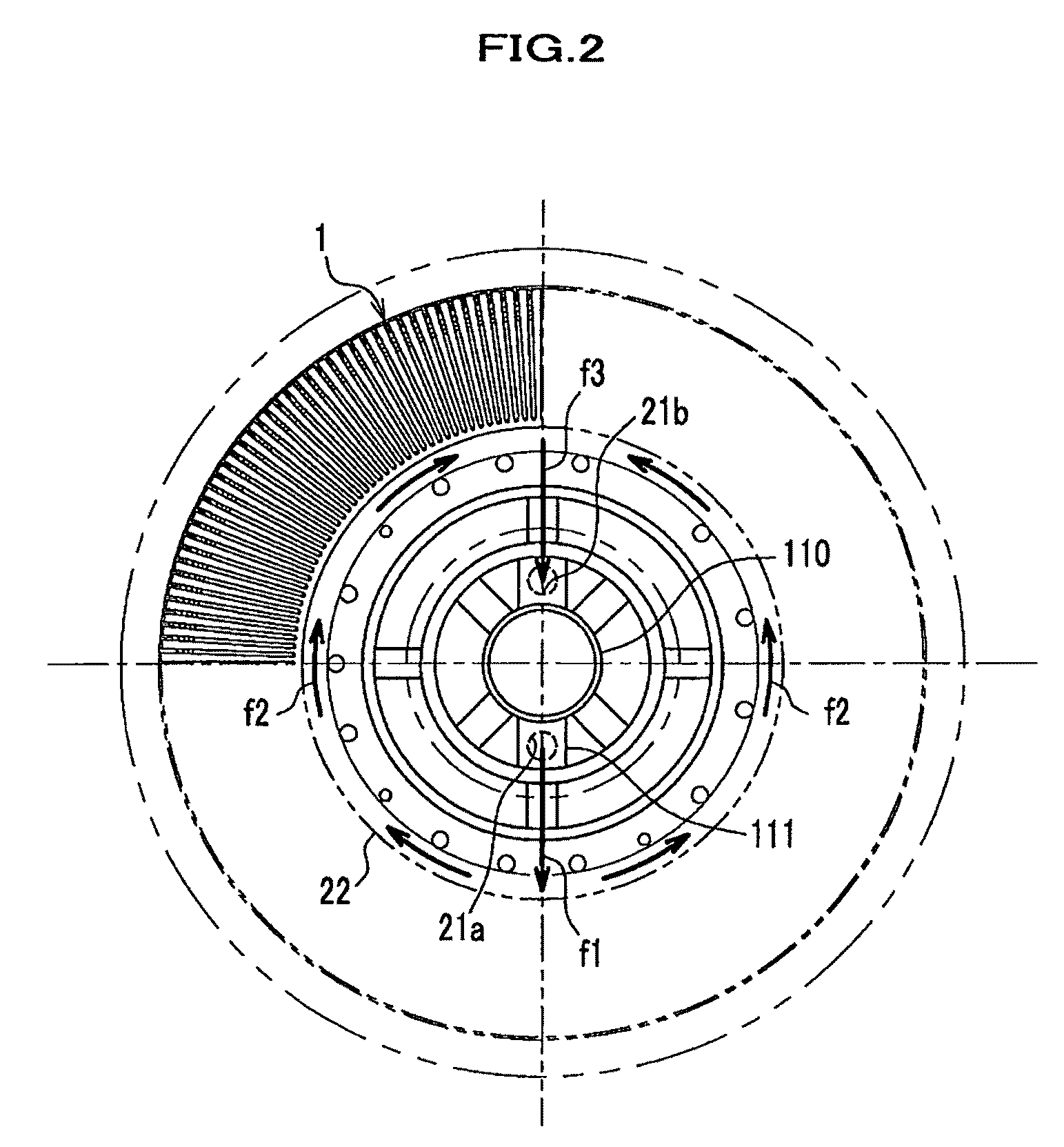
[0072]FIG. 1 shows a structure that a stator according to the embodiment of the present invention is used in a motor. FIG. 2 shows a side view of the stator shown in FIG. 1. FIGS. 3A and 3B show how a magnetic flux transfer member is inserted. FIG. 4A shows a state before first and second coil plates are stacked, and FIG. 4B shows a stacked state. FIG. 5A shows a state where the magnetic flux transfer member is not inserted, and FIG. 5B shows the coil having the magnetic flux transfer member and a heat transfer member. FIG. 6A shows the coil, and FIG. 6B shows a U-phase coil loop virtually removed out.

[0073]FIG. 7A shows a current flow in a first coil plate loop, and FIG. 7B shows a current flow in a second coil plate loop.

[0074]As shown in FIG. 1, a stator 1 (stator for electrical rotating machine) including a coil assembly for an electrical rotating machine according to the embodiment of ...


PUM


Abstract

The torque characteristic is improved using a magnetic flux efficiently, and an eddy-current loss generated in a coil is reduced. Moreover, a loss is suppressed even if a metal member having a high thermal conductivity is closely disposed or closely contacted to a coil surface exposed by a variable magnetic field to improve the heat transfer property, thereby improving the cooling capability. A coil assembly for a rotational electric apparatus has first and second coil plates having wiring patterns formed in such a way that conductive coil segments adjoin with each other via slits, magnetic-flux-transfer-member slots formed in the slits and having a wider width than such slits, a coil constituted by the stacked coil plates so that the magnetic-flux-transfer-member slots overlap with each other, and a magnetic flux transfer member inserted into the magnetic-flux-transfer-member slots of the coil.

Description

CROSS REFERENCE TO RELATED APPLICATIONS[0001]This application claims the foreign priority benefit under Title 35, United States Code, ยง119(a)-(d) of Japanese Patent Application No. 2008-020057, filed on Jan. 31, 2008 in the Japan Patent Office, the disclosure of which is herein incorporated by reference in its entirety.BACKGROUND OF THE INVENTION[0002]1. Field of The Invention[0003]The present invention relates to a coil assembly for an electrical rotating machine, a stator for an electrical rotating machine, and an electrical rotating machine, and more particularly, a coil assembly and a stator for an axial type electrical rotating machine, and the axial type electrical rotating machine.[0004]2. Description of The Related Art[0005]In general, because coreless type electrical rotating machines (electric motors and electric generators) have no iron-based core member, in which magnetic saturation is caused by a coil current, in a coil member, the linearity of torque can be maintained ...

Claims


Application Information

Patent Timeline
06 Aug 2009
Publication
US20090195106A1
IPC
H02K3/04
CPC
H02K3/47; H02K3/26
Inventors
IKI, TOMOTAKA; MURAKAMI, HISASHI