Motor drive device

a technology of motor drive and drive shaft, which is applied in the direction of electric devices, motor/generator/converter stoppers, dynamo-electric converter control, etc., can solve the problems of increasing the rotation speed of the motor, increasing the risk of problems, and destroying the thermal structur

Inactive Publication Date: 2009-08-06
TOYOTA JIDOSHA KK
View PDF6 Cites 55 Cited by
  • Summary
  • Abstract
  • Description
  • Claims
  • Application Information

AI Technical Summary

Benefits of technology

[0011]According to the above motor drive device, an excessive current at the power converting device and the conductive lines caused by a back electromotive force generated at the multi-phase motor can be prevented.
[0013]According to the above motor drive device, the first and second switching elements of the short-circuited arm circuit can be readily fixed to the conducting state.
[0017]According to the above motor drive device, an excessive current at the power converting device and the conductive lines caused by a back electromotive force generated at the multi-phase motor by a rotational force of the drive shaft can be prevented.
[0019]According to the above motor drive device, an excessive current at the power converting device and the conductive lines caused by a back electromotive force generated at the multi-phase motor rotating with rotation of the vehicle driving motor can be prevented.
[0020]According to the present invention, in the motor drive device, the inverter and the conductive lines can be protected from an excessive current caused by a short-circuit fault of the inverter.

Problems solved by technology

Therefore, as the rotation speed of the motor is increased, a current that exceeds a set current value defined by thermal limits and the like of the switching elements and the wire harness flows through the inverter and the conductive line, and these may be thermally destroyed.
These problems are more likely to occur especially when the vehicle runs in the limp mode, is suddenly stopped, and then is towed and carried to an automotive repair shop and the like.
That is, when the vehicle is towed, it is more likely that the rotation speed of the motor becomes higher and the running time becomes relatively longer than those when the vehicle runs in the limp mode where power supply to a drive shaft is, limited.
Therefore, the possibility that the inverter and the wire harness are brought to an excessive current state is increased.

Method used


Image

  • Motor drive device
  • Motor drive device
  • Motor drive device

Examples


Embodiment Construction

[0028]In the following, embodiments of the present invention will be described in detail with reference to the figures. In the figures, the same reference characters denote the same or corresponding portions.

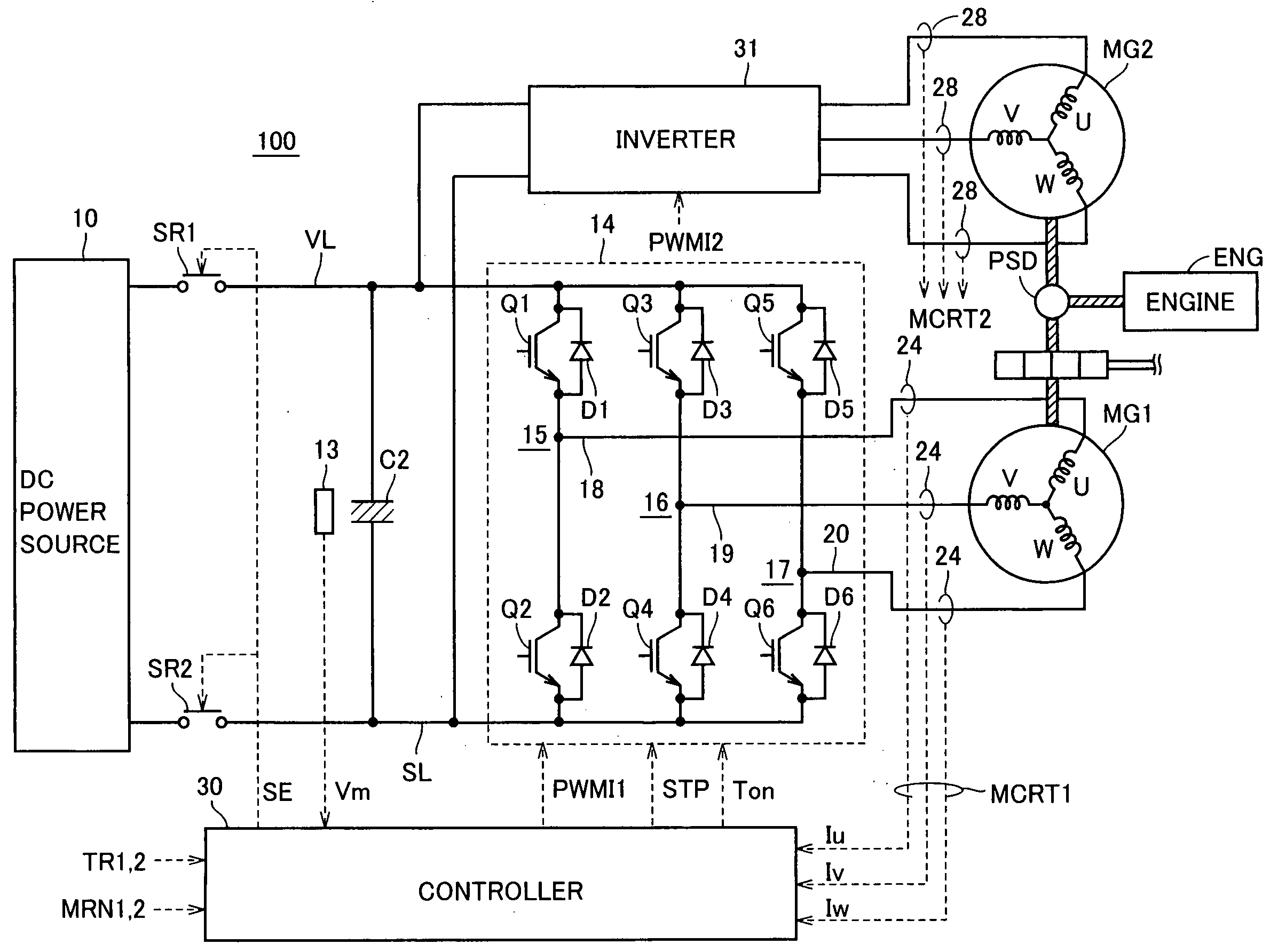
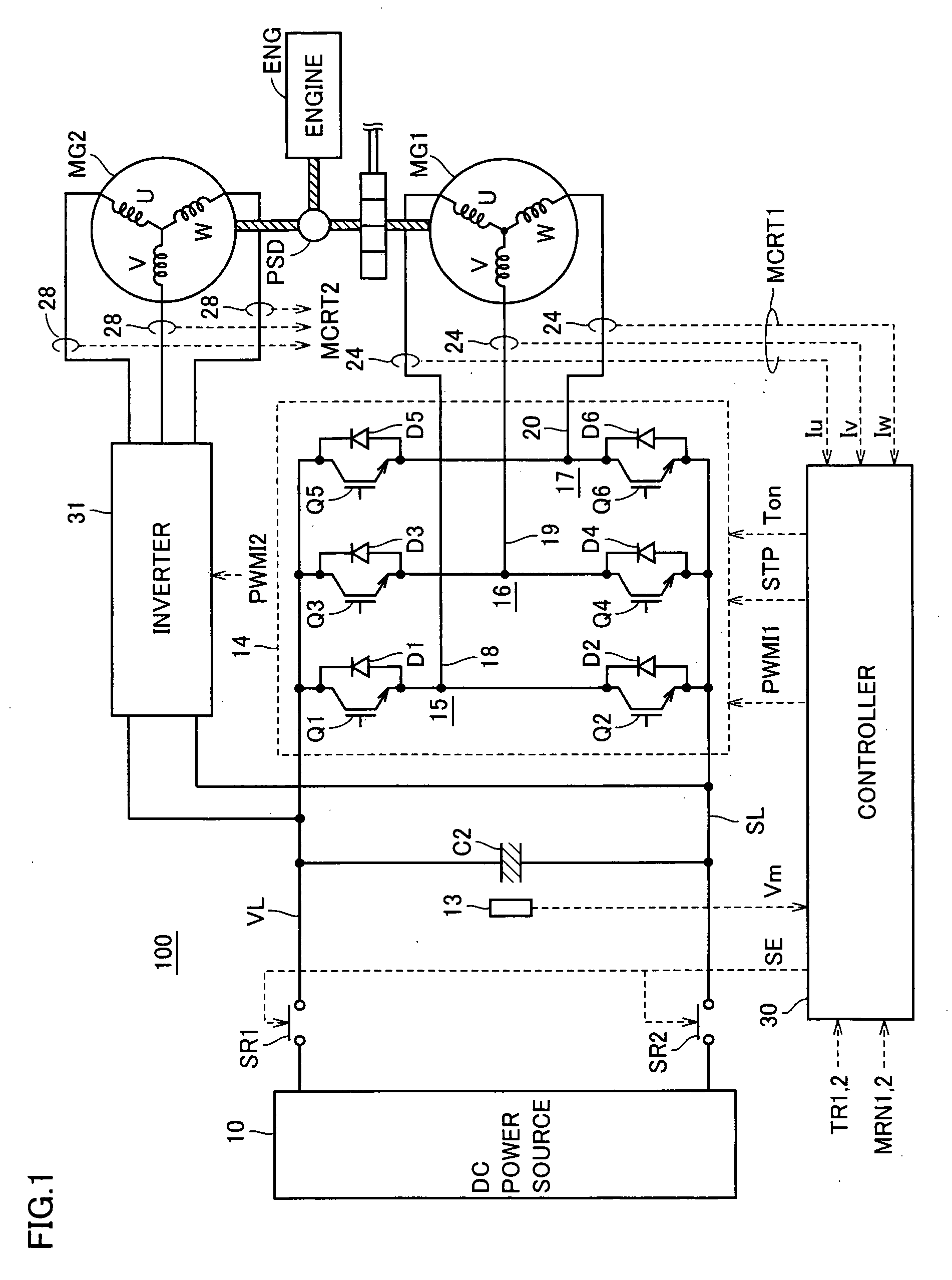
[0029]FIG. 1 is a schematic block diagram of a motor drive device according to an embodiment of the present invention.

[0030]Referring to FIG. 1, a motor drive device 100 includes a DC power source 10, a voltage sensor 13, system relays SR1 and SR2, a capacitor C2, inverters 14 and 31, current sensors 24 and 28, and a controller 30.

[0031]An engine ENG generates driving force using combustion energy of fuel such as gasoline as a source. The driving force generated by engine ENG is split to two routes by a power split device PSD as shown by thick oblique lines in FIG. 1. One route is for transmitting the force through a not-shown reduction device to a drive shaft for driving wheels. The other route is for transmitting the force to a motor generator MG1.

[0032]Motor generators MG1 an...


PUM


Abstract

A controller (30) determines a failure of an inverter (14) in response to detection of an excessive current in any one of IGBT elements of the inverter (14) during driving of a motor generator (MG1). The controller (30) sets the inverter (14) to a suspended state in response to the determination of the failure, and identifies a short-circuited phase based on a motor current (MCRT1) from a current sensor (24). The controller (30) simultaneously turns on two IGBT elements forming upper and lower arms of the short-circuited phase in a discharge process of a capacitor (C2) performed during stop control of a vehicle. Thus, the two IGBT elements are short-circuited because of a rapid increase in heat loss caused by an excessive short-circuit current. As a result, an excessive current at the inverter and power supply lines caused by a back electromotive force generated at the motor generator (MG1) when the vehicle is towed is suppressed.

Description

TECHNICAL FIELD[0001]The present invention relates to a motor drive device, and in particular, to a motor drive device in which overheating caused by a short-circuit fault of a power converting device can be prevented.BACKGROUND ART[0002]Recently, a hybrid vehicle and an electric vehicle are attracting attention as ecologically friendly vehicles. A hybrid vehicle has, as power sources, a DC power source, an inverter and a motor driven by the inverter, in addition to a conventional engine. That is, power is obtained by driving the engine and, in addition, the DC voltage from the DC power source is converted to an AC voltage by the inverter, the motor is rotated by the converted AC voltage, and whereby power is obtained.[0003]An electric vehicle has a DC power source, an inverter and a motor driven by the inverter, as power sources.[0004]In a motor drive device mounted on a hybrid vehicle or an electric vehicle as such, typically, when a failure such as a short-circuit fault of a swit...

Claims


Application Information

Patent Timeline
Patent Type & Authority Applications(United States)
IPC IPC(8): H02H7/08
CPCB60L3/003Y02T10/642H02P29/028H02P29/021H02M7/5387H02P29/0241H02P29/032H02M1/322Y02T10/64
Inventor ITO, YUJI
Owner TOYOTA JIDOSHA KK
Why Eureka
Try Eureka