
Printing control device, print data generation device, printing system and printing control program

a printing control and data generation technology, applied in the direction of colour-separation/tonal correction, instruments, digitally marking record carriers, etc., can solve the problems of printing under unsuitable printing conditions, printer colors (the ink volumes of c, m, y, k, o and g) for achieving spectral reproducibility not necessarily optimal in relation to printing performance factors, and overall increase in the consumption of coloring materials such as ink, so as to achieve high spectral reprodu

Active Publication Date: 2009-08-06
SEIKO EPSON CORP
View PDF4 Cites 16 Cited by
  • Summary
  • Abstract
  • Description
  • Claims
  • Application Information

AI Technical Summary

Benefits of technology

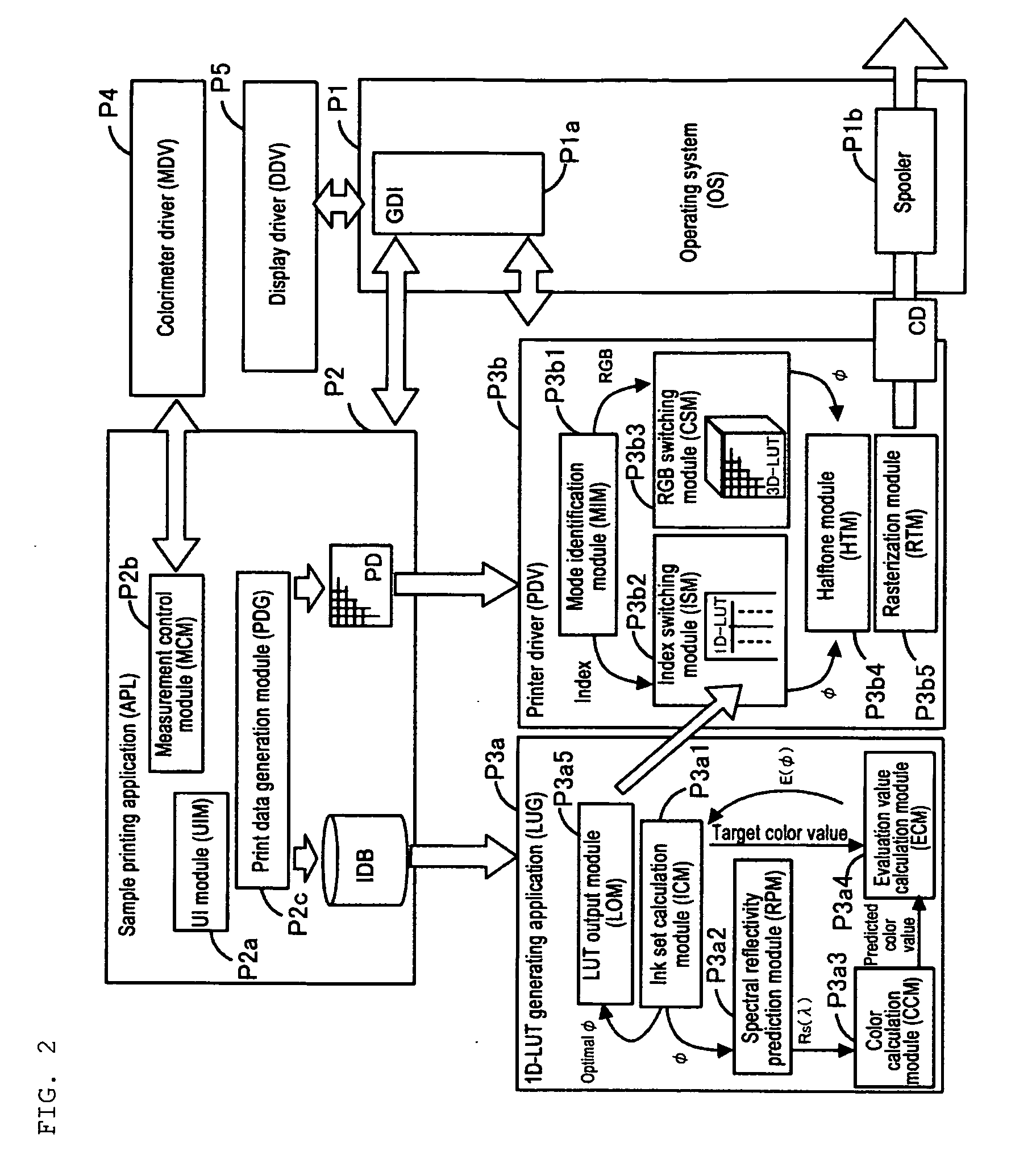
[0010]Furthermore, it is preferable that the coloring material volume set associated with the index is a coloring material volume set which produces a prescribed target spectral reflectivity or a target prescribed color value under a plurality of light sources, as a result of printing on the recording medium. By taking the actual spectral reflectivity that is reproduced on the recording medium as the target, it is possible to obtain print results which have high spectral reproducibility in respect of the prescribed pixels. Furthermore, by taking the color values under a plurality of light sources as the target of the spectral reproducibility, it is possible to achieve color reproducibility which is not dependent on the light source, and consequently it is possible to achieve spectral reproducibility.

Problems solved by technology

In cases such as these, it is thought that drawbacks of the following kind will arise if spectral reproducibility is also achieved unnecessarily in regions where spectral reproducibility is not required.
Firstly, there is a drawback in that printing is carried out under unsuitable printing conditions.
This is because the printer colors (the ink volumes of C, M, Y, K, O and G) for achieving spectral reproducibility are not necessarily optimal in relation to printing performance factors apart from the object of achieving spectral reproducibility.
For example, due to the demand for spectral reproducibility, there have been problems such as an overall increase in the consumption of coloring material, such as ink, decline in the tonal characteristics of the reproduced colors, and so on.
Secondly, there is a conceivable drawback in that the calculation processing load is increased unnecessarily.
In other words, since it is necessary to optimize a large number of variable amounts in calculating the printer colors (the C, M, Y, K, O and G ink volumes) which allow reproduction of the target spectral reflectivity, then a problem arises in that the processing load increases if spectral reproducibility is sought for all of the pixels used in the printed image.

Method used


Image

  • Printing control device, print data generation device, printing system and printing control program
  • Printing control device, print data generation device, printing system and printing control program
  • Printing control device, print data generation device, printing system and printing control program

Examples


modification examples

5. MODIFICATION EXAMPLES

5-1. Modification Example 1

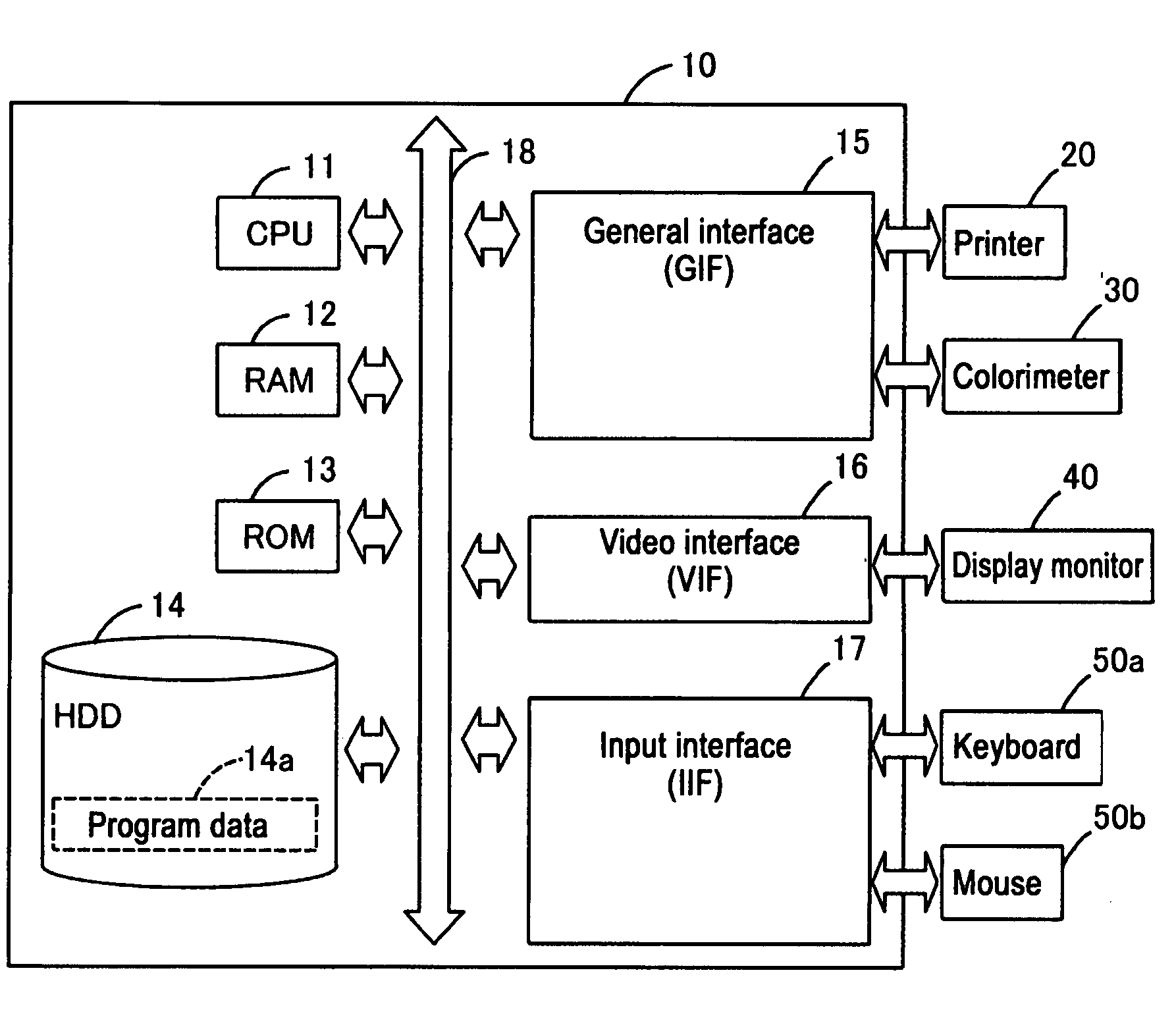
[0105]In Formula (2), the weighting coefficients for the light sources w1 to w5 are set to equal values, but it is also possible to the weighting coefficients w1 to w5 to different values. If the weighting coefficients w1 to w5 are set to larger values, then it is possible to raise the degree to which the color differences ΔED50, ΔED55, ΔED65, ΔEA, ΔEF11 of the corresponding light sources contribute to the increase in the evaluation value E(φ). Consequently, in order to minimize the evaluation value E(φ), it is necessary to ensure a particularly small value for the color differences ΔED50, ΔED55, ΔED65, ΔEA, ΔEF11 for those light sources which have been set to a high weighting coefficient w1 to w5, and by using an ink volume set φ which has been optimized on the basis of this evaluation value E(φ), it is possible to achieve printing which reduces the color differences ΔED50, ΔED55, ΔED65, ΔEA, ΔEF11 for the light sources which are s...

modification example 2

5-2. Modification Example 2

[0107]In the embodiment described above, the target color values of the target TG under the plurality of light sources are specified by means of a calorimeter 30, but it is also possible for the user to specify the target color values directly via the keyboard 50a, or the like. For example, if color value data obtained by previous color measurement of the target TG has already been prepared, or the like, then it is possible to specify the target color values by inputting this data. Moreover, since the target color values under the plurality of light sources can be calculated uniquely on the basis of the spectral reflectivity R(λ) of the target TG, then it is also possible to measure the spectral reflectivity R(λ) of the target TG by means of a spectral reflectometer instead of color measurement by a colorimeter 30 at step S140.

[0108]FIG. 20 shows a schematic view of the procedure for calculating the target color values in a case where the spectral reflecti...

modification example 3

5-3. Modification Example 3

[0109]FIG. 21 shows a schematic view of a case where the CCM P3a3 calculates predicted color values on the basis of the predicted spectral reflectivity Rs(λ) in a modification example. FIG. 21 shows the target spectral reflectivity Rt(λ) obtained in the modification example described above, and the correlation coefficients cx, cy, cz between this target spectral reflectivity Rt(λ) and the respective isochromatic functions x(λ), y(λ), z(λ) are calculated by the CCM P3a3. Since the isochromatic functions x(λ), y(λ), z(λ) respectively assume large values in different wavebands, then it can be considered that the correlation coefficients cx, cy, cz will become high when the waveband where the isochromatic function assumes a large value is similar to the target spectral reflectivity Rt(λ). The predicted color value according to the embodiment can be calculated by Formula (6) below.

Expression 6

[0110]

X=k∫P(λ)Rs(λ)cxx(λ)dλ

Y=k∫P(λ)Rs(λ)cyy(λ)dλ

Z=k∫P(λ)Rs(λ)czz(λ)dλ...


PUM

PropertyMeasurementUnit
volumeaaaaaaaaaa
coloraaaaaaaaaa
volumesaaaaaaaaaa

Abstract

A printing control device that specifies to a printing apparatus a coloring material volume set which is a combination of usage amounts of coloring materials when the printing apparatus executes printing by depositing a plurality of coloring materials onto a recording medium, including: a print data acquisition unit that acquires print data of pixels having an information area for storing an index associated with the coloring material volume set; a color conversion unit that acquires the coloring material volume set corresponding to the index stored in the pixel; and a printing control unit that executes printing by specifying to the printing apparatus the coloring material volume set acquired by the color conversion unit.

Description

CROSS-REFERENCE TO RELATED APPLICATIONS[0001]The entire disclosure of Japanese Patent Application No. 2007-330785, filed Dec. 21, 2007, and Japanese Patent Application No. 2008-306357, filed Dec. 1, 2008, are expressly incorporated by reference herein.BACKGROUND[0002]1. Technical Field[0003]The present invention relates to a printing control device, a print data generation device, a printing system and printing control program, and more particularly, to a printing control device, a print data generation device, a printing system and a printing control program for reproducing a target.[0004]2. Related Art[0005]JP-T-2005-508125 proposes a printing method which pays particular attention to spectral reproducibility. According to JP-T-2005-508125, in order to achieve printing which coincides with a target image both spectrally and calorimetrically, a printing model is used to optimize the combination of printer colors (the ink volumes of C, M, Y, K, O and G) in order to match a target sp...

Claims


Application Information

Patent Timeline
Patent Type & Authority Applications(United States)
IPC IPC(8): G03F3/08
CPCH04N1/6033H04N1/04
Inventor HOSHII, JUNITO, TAKASHINAKAJIMA, HISANORISAKA, KAZUHISAISHIDA, MASANORITOKUTOMI, FUMIO
Owner SEIKO EPSON CORP
Learn More